


When your engine stalls unexpectedly, the root cause typically lies in either the fuel system or the ignition system—two fundamentally different systems that produce distinct failure patterns. Fuel system stalling occurs when the engine is starved of adequate fuel delivery, resulting in gradual power loss, sputtering, and hesitation before the engine dies. In contrast, ignition system stalling happens when spark generation fails, causing the engine to cut out suddenly and completely without warning signs. Understanding the specific diagnostic clues that differentiate these two failure modes empowers drivers to identify the problem system quickly, avoid unnecessary repairs, and communicate effectively with mechanics about the actual issue.
The eight key diagnostic clues revealed in this article provide a systematic framework for stalling diagnosis, ranging from restart behavior patterns to temperature-dependent failure characteristics. Each clue represents an observable symptom that points toward either fuel delivery problems—such as clogged fuel filters, failing fuel pumps, or malfunctioning fuel injectors—or ignition failures like worn spark plugs, heat-damaged ignition coils, or faulty crankshaft position sensors. By methodically evaluating these diagnostic indicators, vehicle owners can narrow down the problem system before investing in diagnostic services or replacement parts.
Beyond identifying symptoms, this guide provides practical testing procedures that drivers can perform with basic tools to confirm whether the fuel system or ignition system is responsible for stalling events. These step-by-step diagnostic tests include checking fuel pump operation, measuring fuel pressure, inspecting spark plug condition, and testing ignition coil resistance. Understanding which components most commonly fail within each system—and recognizing the cost implications of various repair scenarios—helps drivers make informed decisions about repair priorities and budgeting.
Finally, Safe response when vehicle stalls in traffic and preventive maintenance strategies complete the comprehensive approach to managing stalling issues. Next, let’s explore the fundamental differences between fuel system and ignition system stalling patterns to establish a foundation for accurate diagnosis.
What Is the Difference Between Fuel System and Ignition System Stalling?
Fuel system stalling occurs when the engine receives insufficient fuel for combustion, manifesting as gradual power loss, sputtering sounds, and hesitation before the engine dies, while ignition system stalling results from spark generation failure, causing immediate and complete engine cutoff without warning. Specifically, these two failure modes differ in their mechanical origins, symptom presentation, and failure progression patterns.
Fuel system stalling originates from disruptions in the fuel delivery pathway from tank to combustion chamber. The fuel pump must maintain adequate pressure—typically between 40-60 PSI for most modern vehicles—to push gasoline through the fuel filter, fuel lines, and into the fuel injectors. When any component in this chain fails or becomes restricted, the engine experiences fuel starvation. A clogged fuel filter creates resistance that the pump cannot overcome, particularly under acceleration or high-load conditions. A weakening fuel pump may generate sufficient pressure at idle but fail to deliver adequate fuel volume when engine speed increases. Leaking or clogged fuel injectors disrupt the precise fuel metering required for proper combustion. The result is an air-fuel mixture that becomes progressively leaner—too much air, insufficient fuel—until combustion can no longer sustain itself and the engine stalls.
The characteristic symptoms of fuel system stalling include engine sputtering, which sounds like irregular firing or “coughing” as cylinders intermittently receive inadequate fuel. Drivers often notice hesitation during acceleration, where depressing the throttle produces delayed or weak response. Power loss occurs gradually rather than instantaneously, giving drivers a few seconds of warning before the engine dies completely. In many cases, the engine may recover briefly if throttle input is reduced, indicating that fuel delivery can meet idle demands but not acceleration requirements.

Ignition system stalling stems from failures in the spark generation and delivery mechanism. The ignition system transforms the battery’s 12-volt current into 30,000-50,000 volts through ignition coils, then routes this high-voltage electricity to spark plugs at precisely timed intervals controlled by the engine control module (ECM). Critical components include the crankshaft position sensor—which tells the ECM exactly when each cylinder reaches the optimal spark timing position—ignition coils that generate high voltage, spark plug wires that transport this voltage, and spark plugs that create the actual arc across their electrode gap to ignite the compressed air-fuel mixture. When any component in this electrical chain fails, spark cannot reach one or more cylinders, disrupting combustion.
Unlike the gradual degradation of fuel system stalling, ignition system failures typically produce sudden, complete engine shutdown. The engine runs normally one moment, then dies instantly the next, as if someone turned off the ignition key. There is no sputtering, no gradual power loss, no warning hesitation. The engine simply stops firing. This sudden death pattern occurs because ignition components tend to fail completely rather than partially—an ignition coil either generates sufficient voltage or it doesn’t, a crankshaft position sensor either sends its signal or it doesn’t. The binary nature of electrical component failure creates the characteristic instantaneous stall.
Temperature sensitivity represents another key differentiator between these systems. Ignition components, particularly ignition coils and electronic modules, are highly susceptible to heat-related failure. An ignition coil may function perfectly when cool but develop internal resistance or short circuits when heated by engine operation, causing stalling after 15-30 minutes of driving. The crankshaft position sensor, mounted near the engine’s rotating components, can experience similar heat-induced failures. Conversely, fuel system components show different temperature relationships. Vapor lock—where excessive heat causes fuel to vaporize in the fuel lines before reaching the injectors—can cause hot-weather stalling, while cold temperatures may affect fuel viscosity and starting enrichment systems.
The mechanical differences extend to how each system responds to engine load. Fuel system problems typically worsen under acceleration and high-load conditions because fuel demand increases dramatically when the driver requests more power. A marginally adequate fuel pump or partially clogged fuel filter may sustain idle and cruise conditions but fail completely when asked to supply fuel for acceleration. Ignition system problems show less correlation with load and more association with specific operating conditions like idle speed, where low electrical system voltage or specific timing windows may expose component weaknesses.
Understanding these fundamental mechanical differences provides the foundation for accurate stalling diagnosis. When a driver can recognize whether their stalling pattern matches the gradual, sputtering fuel starvation profile or the sudden, complete ignition failure profile, they’ve already narrowed the diagnostic field significantly. The following sections detail eight specific diagnostic clues that further refine this differentiation and point to exact component failures.
What Are the 8 Key Diagnostic Clues That Reveal Whether Fuel or Ignition Is Causing Your Stall?
The eight key diagnostic clues for differentiating fuel system from ignition system stalling are: stall progression pattern (sudden vs. gradual), restart behavior, speed-dependent occurrence, failure consistency, temperature correlation, diagnostic trouble codes, sensory indicators, and throttle response during stalling events. To better understand how each clue reveals the underlying problem system, let’s examine them individually with specific failure indicators.
Does Your Engine Sputter Before Stalling or Die Suddenly?
Engine sputtering before stalling indicates fuel system problems, while sudden engine death without warning points to ignition system failure. The distinction between these two patterns represents the single most reliable initial diagnostic clue for identifying the problem system.
Sputtering manifests as irregular engine firing—a rhythmic “miss” or “cough” where the engine’s normal smooth operation becomes choppy and uneven. This sound occurs because individual cylinders intermittently receive insufficient fuel to maintain combustion. When the fuel-air mixture becomes too lean in a cylinder, that cylinder fails to fire properly during its power stroke, creating a momentary loss of power contribution. As fuel starvation worsens across multiple cylinders, the cumulative effect produces the characteristic sputtering sound. The engine is literally struggling to maintain combustion with inadequate fuel supply. Most drivers describe this as the engine “running rough” or “missing” before it finally quits. The sputtering period may last anywhere from 2-10 seconds before complete stalling, giving drivers warning time to safely navigate to the roadside.
The sputtering pattern directly correlates with fuel delivery inadequacy. A fuel filter that has accumulated debris and contamination creates progressive restriction—at first reducing fuel flow slightly, then increasingly as pressure builds and filtration material compresses. The partially starved engine sputters. A fuel pump with wearing internal components may produce intermittent pressure pulses rather than steady pressure, causing sporadic fuel delivery that manifests as sputtering. Fuel injectors experiencing partial clogging spray fuel in irregular patterns—sometimes adequate, sometimes insufficient—producing the miss-fire-miss-fire pattern drivers hear as sputtering.
Sudden engine death presents the opposite characteristic. The engine operates normally with smooth power delivery, then abruptly stops firing as if the ignition key was turned off. There is no warning sputtering, no gradual power decline, no opportunity to recognize impending stalling. The transition from normal operation to complete shutdown occurs in less than one second. This instantaneous failure indicates complete loss of spark to the cylinders, which can only occur through ignition system component failure.
Common ignition failures producing sudden death include crankshaft position sensor malfunction, where the ECM instantly loses the critical signal telling it when to fire each cylinder. Without position reference, the ECM cannot command ignition coil firing, and all spark ceases immediately. Similarly, ignition module failure—whether a standalone module or the electronics within the ECM itself—can interrupt the trigger signal to ignition coils, stopping spark generation across all cylinders simultaneously. Even individual ignition coil failure can produce sudden stalling if the engine cannot maintain sufficient power with one or more dead cylinders, though this more commonly causes severe misfiring rather than complete stalling.
The sudden-death pattern also applies to electrical supply interruptions. A loose or corroded main power connector to the ignition system, an intermittent ignition switch contact failure, or a main relay dropout all cut power instantaneously, killing the engine without warning. These electrical failures share the ignition system’s characteristic of binary operation—power flows or it doesn’t, with no middle ground producing gradual degradation.
Drivers experiencing stalling should mentally replay the final seconds before engine shutdown. Did the engine feel progressively weaker, sound increasingly rough, seem to “struggle” before dying? That’s fuel system starvation. Or did the engine run perfectly normally, then simply stop as if switched off? That points to ignition system electrical failure. This single observation often provides 70-80% diagnostic certainty about which system requires attention.
Can You Restart Immediately After Stalling?
Immediate restart capability after stalling typically indicates fuel system issues, while delayed or failed restart attempts point to ignition system component failure. However, the specific restart behavior pattern provides even more granular diagnostic information about the exact component causing the problem.
When fuel system components cause stalling, the engine usually restarts within seconds of the stalling event. This occurs because most fuel system failures are pressure-related rather than complete blockages. For example, a weak fuel pump may fail to maintain adequate pressure under the load of highway speed driving, allowing the engine to stall. But when the engine stops, fuel demand drops to zero, and the pump can rebuild pressure in the fuel rail during the 5-10 seconds the driver takes to safely pull over and attempt restart. Upon cranking, adequate fuel pressure exists briefly, the engine starts, and may even idle normally for 30-60 seconds before pressure again drops below the threshold needed to sustain operation. This restart-then-stall pattern strongly indicates fuel pump weakness.
Similarly, a clogged fuel filter creates flow restriction that becomes critical under high-demand conditions. When the engine stalls and stops drawing fuel, pressure equalizes across the filter. The initial restart attempt may succeed because the pressure differential hasn’t yet developed. But as soon as the engine begins running and pulling fuel through the restriction, pressure drops, and stalling recurs. Drivers experiencing this pattern often report they can restart and idle for a short period, but the engine dies again when attempting to drive.
Fuel system restart patterns also include the phenomenon where repeatedly cycling the ignition key (without cranking) primes the fuel pump multiple times, building extra fuel pressure that allows successful restart and potentially several minutes of driving before the next stall. This “pump primer” method becomes a telling diagnostic sign of fuel pressure-related stalling.
Ignition system failures typically prevent immediate restart or allow restart only after a specific waiting period. The most common pattern involves heat-related component failure. An ignition coil with internal winding insulation breakdown operates correctly when cool but develops internal short circuits as heat builds during operation. After 20-30 minutes of driving, the coil overheats and fails, causing stalling. Attempting immediate restart fails because the coil remains too hot. However, if the driver waits 10-15 minutes for the coil to cool below its failure threshold, restart succeeds—until the next heat cycle produces another failure. This cool-down-required restart pattern strongly indicates heat-sensitive ignition components.
Crankshaft position sensors exhibit similar heat sensitivity. These sensors contain electronic components and magnetic windings that can develop heat-induced failures. The sensor works perfectly cold, begins intermittent failure as it heats, and eventually stops sending position signals entirely when critically overheated. Immediate restart fails because the sensor remains above its failure temperature. After cooling for several minutes, the sensor recovers functionality and restart succeeds.
Some ignition failures prevent restart entirely until repairs are completed. A completely failed ignition coil that has developed an internal open circuit cannot generate spark regardless of temperature. A crankshaft position sensor with a broken internal wire provides no signal whether hot or cold. These complete failures result in cranking that produces no start whatsoever—the engine turns over normally but never fires. This crank-no-start condition indicates terminal component failure requiring replacement.
A notable exception exists: intermittent electrical connection problems in the ignition system may allow immediate restart if the bad connection temporarily re-establishes contact during the restart process. A corroded ignition coil connector might lose contact during vibration while driving, causing stalling, but when the engine stops and vibration ceases, spring tension in the connector re-establishes contact, allowing restart. These intermittent connection issues often produce seemingly random stalling that doesn’t follow consistent temperature or load patterns.
Drivers should document their restart experience carefully: How long after stalling before successful restart? Does waiting help or make no difference? Can the engine be restarted immediately but then stalls again quickly? These restart behavior patterns provide critical diagnostic information that, combined with other clues, significantly narrow the component-level diagnosis.
Does Stalling Occur at Idle, Acceleration, or Highway Speed?
Stalling at idle suggests idle air control valve issues or ignition problems specific to low-RPM operation, acceleration stalling indicates fuel delivery restriction or weak fuel pump, while highway speed stalling points to ignition coil heat failure or fuel pump volume inadequacy. The specific speed or load condition when stalling occurs reveals which components are most likely to fail under those operating conditions.
Idle stalling presents unique diagnostic challenges because multiple systems converge to maintain stable idle speed. The engine control module must balance fuel delivery, ignition timing, and idle air bypass to maintain the target idle RPM—typically 600-900 RPM depending on vehicle. At these low speeds, the engine produces minimal vacuum and airflow, making it particularly sensitive to small disruptions.
The idle air control (IAC) valve regulates the amount of air bypassing the closed throttle plate to maintain proper idle speed. Carbon deposits can accumulate in the IAC valve passages, reducing airflow and causing RPM to drop below sustainable levels, resulting in stalling. This issue manifests specifically at idle because the IAC only operates when the throttle is closed. During driving with open throttle, adequate air enters through the main throttle bore and the IAC restriction becomes irrelevant. Cleaning or replacing the IAC valve typically resolves idle-specific stalling.
Vacuum leaks and stalling correlation becomes particularly relevant at idle. A vacuum leak allows unmetered air to enter the intake manifold, bypassing the mass airflow sensor (MAF) or manifold absolute pressure (MAP) sensor that measures incoming air. The ECM calculates fuel delivery based on sensor readings, but actual air entering the engine exceeds measured air due to the leak. This creates a lean condition—excess air, insufficient fuel. At idle, even small vacuum leaks produce enough mixture imbalance to cause stalling, while at higher engine speeds, increased throttle opening provides enough extra fuel to compensate for the leak. Common vacuum leak sources include deteriorated intake manifold gaskets, cracked vacuum hoses, and leaking brake booster diaphragms.
Idle-specific ignition issues typically involve insufficient voltage at low RPM. The alternator generates less charging voltage at idle speed than at higher RPMs. If the battery is weak or the alternator is marginal, available voltage at idle may drop below the threshold required for ignition coils to generate full spark energy. Weak spark produces incomplete combustion, rough idle, and eventual stalling. Increasing engine speed by slightly opening the throttle raises alternator output, voltage increases, spark strength improves, and the engine runs smoothly—until returning to idle.
Acceleration stalling reveals fuel delivery system inadequacy. When the driver demands power by pressing the accelerator pedal, fuel requirements increase dramatically—often doubling or tripling compared to idle consumption. A fuel pump producing marginal pressure at idle may completely fail to meet acceleration demands. The engine begins to accelerate, fuel demand outpaces supply, air-fuel mixture becomes dangerously lean, combustion fails, and the engine stalls. This pattern specifically identifies fuel pump weakness or fuel filter restriction.
Clogged fuel filters produce classic acceleration stalling. The filter may pass sufficient fuel for idle and light cruise but cannot flow enough volume for hard acceleration. As fuel demand spikes, pressure drops across the restricted filter, fuel rail pressure plummets, injectors cannot deliver adequate fuel, and stalling occurs. The stalling moment often coincides precisely with the instant of maximum acceleration demand—pulling onto a highway, climbing a steep hill, or merging into traffic.
Fuel injector restrictions also manifest during acceleration. Partially clogged injectors may spray enough fuel for idle operation but cannot deliver the pulse width and volume required for acceleration enrichment. Unlike fuel pump or filter issues that affect all cylinders equally, clogged injectors typically affect one or two cylinders, producing severe misfire during acceleration that may not quite stall the engine but causes dramatic power loss and rough operation.
Highway speed stalling almost exclusively indicates ignition system heat failure or fuel pump volume limitation. At sustained highway speeds—55-75 MPH—the engine operates at consistent moderate RPM (typically 2000-3000 RPM) for extended periods. This consistent operation generates continuous heat in both the engine compartment and specific components.
Ignition coils mounted directly on the engine (coil-on-plug designs) experience extreme heat exposure during highway driving. Modern ignition coils contain epoxy-potted electronic components and copper windings that gradually degrade with heat cycles. A coil approaching end-of-life may function correctly for the first 15-20 minutes of driving, but as internal temperature rises above 200°F, insulation begins breaking down, internal resistance increases, and output voltage drops. Eventually, the coil cannot generate sufficient voltage to fire its spark plug, that cylinder stops contributing power, and if multiple coils fail or the engine can’t sustain operation on reduced cylinder count, complete stalling results. The stalling typically occurs after consistent highway driving duration—often remarkably predictable, like “always after 25 minutes on the interstate.”
Fuel pump heat failure follows similar patterns. Fuel pumps are cooled by the gasoline flowing through them. At highway speeds with consistent fuel flow and minimal tank turbulence, heat buildup occurs in the pump motor and electronics. Pumps near end-of-life may develop heat-sensitive internal components that fail after specific operating durations. The pump stops, fuel pressure drops immediately to zero, and the engine stalls within 1-2 seconds. After cooling for 10-15 minutes, restart succeeds until the next heat cycle.
Fuel pump volume limitation represents another highway-speed issue. Some failing pumps maintain adequate pressure but cannot flow sufficient volume. At idle and low speeds, volume requirements are modest and the pump keeps up. But sustained highway speed requires continuous high fuel volume. A pump with worn internal impellers or damaged check valves may produce correct pressure initially but cannot sustain volume flow. Over time—often 15-30 minutes—fuel rail volume depletes faster than the pump replenishes it, pressure drops, and stalling occurs.
Understanding the speed/load correlation with stalling provides powerful diagnostic direction. Idle stalling: investigate IAC valve, vacuum leaks, low-speed ignition voltage. Acceleration stalling: focus on fuel pump, fuel filter, fuel pressure. Highway speed stalling: test ignition coils for heat failure, evaluate fuel pump volume and heat sensitivity. This speed-based diagnostic approach eliminates entire categories of potential causes and directs testing toward the most probable failures.
Is the Stalling Pattern Intermittent or Consistent?
Intermittent stalling patterns typically indicate heat-sensitive ignition system components like crankshaft position sensors and ignition coils, while consistent, repeatable stalling points to fuel system restrictions such as clogged fuel filters or continuously weak fuel pumps. More specifically, the predictability and repeatability of stalling events reveals whether the underlying failure is condition-dependent or permanent.
Intermittent stalling frustrates both drivers and technicians because the problem doesn’t occur on demand during diagnostic testing. The vehicle stalls unexpectedly, restarts after cooling or sitting, then operates perfectly for hours or days before stalling again. This pattern strongly suggests temperature-sensitive component failure, with ignition system components being the primary culprits.
Crankshaft position sensors represent the most common intermittent stalling cause. These sensors use magnetic induction to detect the passing of teeth on the crankshaft reluctor wheel, generating an AC voltage signal that the ECM interprets as crankshaft position and speed information. The sensor contains fine copper windings and electronic components susceptible to heat damage. As the sensor heats during operation—either from radiant engine heat or from electrical resistance in its own windings—internal insulation can break down, creating short circuits or open circuits that intermittently interrupt the signal. The ECM loses position reference and cannot command spark or fuel injection, causing immediate stalling.
The intermittent nature occurs because the failure is temperature-threshold dependent. The sensor works perfectly below a certain temperature, begins intermittent failure in a narrow temperature range, and fails completely when critically overheated. External conditions affect this pattern: ambient temperature, engine load, driving duration, and even airflow around the sensor. A sensor that fails after 30 minutes of summer driving might operate for 2 hours in winter temperatures. This variability makes intermittent problems notoriously difficult to reproduce in shop environments.
Ignition coils exhibit similar intermittent heat failure. The epoxy potting compound inside coils undergoes thermal expansion and contraction with heat cycles. After thousands of cycles over years of use, micro-cracks develop in the epoxy, creating pathways for internal arcing between windings. When cool, the cracks are tight enough that insulation remains adequate. As heat builds and epoxy expands, cracks widen, insulation fails, internal arcing begins, and coil output drops. Stalling results if enough coils fail or if the single-coil failure occurs in a small engine that cannot sustain operation with one dead cylinder. Cooling allows epoxy contraction, cracks close, insulation recovers, and the coil functions again—until the next heat cycle.
Intermittent electrical connections also produce random stalling. Corroded connector terminals, vibration-loosened connector locks, or fatigued wire terminals create resistance or open circuits intermittently. Vibration while driving may separate a marginal connection, causing stalling. When the vehicle stops and vibration ceases, the connection re-establishes, allowing restart. These issues often correlate with rough road conditions, potholes, or specific vibration frequencies that occur at certain speeds.
Consistent, repeatable stalling presents the opposite diagnostic profile. The stalling occurs predictably under specific conditions: always during acceleration, always after specific driving duration, always at idle. This repeatability indicates permanent component degradation rather than temperature or vibration sensitivity.
Clogged fuel filters produce highly consistent stalling patterns. The restriction level is fixed—the debris and contamination in the filter don’t change between driving sessions. Every time fuel flow demand exceeds the filter’s flow capacity, pressure drops below the critical threshold and stalling occurs. This creates a repeatable pattern: “Always stalls when accelerating hard,” or “Always stalls after driving 10 minutes at highway speed.” The consistency reflects the permanent nature of the restriction.
Continuously weak fuel pumps also create consistent patterns. A pump with worn impellers produces the same reduced pressure and volume every time it operates. If this output is marginally adequate for idle but insufficient for highway speed, the stalling will occur consistently at highway speeds. Unlike intermittent heat-sensitive pump failures, a mechanically worn pump produces the same inadequate performance hot or cold, making the stalling predictably repeatable.
Severely clogged fuel injectors follow consistent patterns as well. An injector restricted by carbon deposits and fuel varnish sprays the same inadequate fuel quantity every operating cycle. The affected cylinder(s) run lean continuously, producing chronic misfire that may cause stalling under load. The condition doesn’t vary with temperature or duration—it’s permanently degraded until cleaned or replaced.
Vacuum leaks create consistent idle stalling. The leak size doesn’t change, so the air-fuel ratio imbalance remains constant. Every time the engine idles, the mixture is too lean by the same amount, causing the same rough idle and eventual stalling. Consistency is the hallmark of permanent mechanical problems versus intermittent electrical or heat-related failures.
Drivers documenting their stalling patterns should track: Does it happen at the same point in every drive, or randomly? Does it always correlate with specific conditions (hot weather, after 20 minutes, during acceleration), or does it seem unpredictable? Answering these questions about consistency versus intermittency immediately divides the diagnostic approach into heat/electrical investigation for intermittent issues or mechanical/restriction investigation for consistent problems.
Does the Engine Stall When Hot or Cold?
Hot engine stalling indicates heat-sensitive ignition coils, crankshaft position sensors, or vapor lock in the fuel system, while cold engine stalling points to faulty coolant temperature sensors, idle enrichment issues, or cold-thickened fuel delivery problems. The temperature correlation provides critical diagnostic information because many automotive components have distinct failure characteristics at different operating temperatures.
Hot engine stalling manifests after the engine reaches full operating temperature—typically after 15-30 minutes of driving. The stalling may occur during highway cruising, at idle in traffic, or immediately after shutting off a hot engine and attempting restart (heat soak condition). Several failure mechanisms produce hot-stalling patterns.
Ignition coil heat failure represents the most prevalent hot-stalling cause. Modern coil-on-plug ignition systems mount individual coils directly atop spark plugs, positioning them in the hottest region of the engine compartment. Heat radiates from the cylinder head, exhaust manifolds, and engine block, with underhood temperatures exceeding 250°F during normal operation. Ignition coils contain copper windings wrapped around iron cores and encapsulated in epoxy resin for insulation. As coils age and accumulate heat cycles, the epoxy develops micro-cracks that widen when heated. At operating temperature, these cracks allow electrical arcing between windings, short-circuiting the coil and preventing voltage buildup. The coil functions perfectly when cold and epoxy cracks are contracted, but fails predictably after reaching critical temperature.
Crankshaft position sensor heat failure follows similar physics. These sensors mount near rotating engine components—crankshaft or camshaft—in high-heat zones. Sensor windings and internal electronics degrade with heat exposure. A sensor approaching end-of-life operates correctly at startup and during initial driving, but as it absorbs radiant engine heat and heat from its own electrical resistance, internal components fail. The ECM loses position signal, cannot command ignition or injection timing, and the engine stalls immediately. Heat soak after shutdown presents particular problems—turning off a hot engine stops cooling airflow from driving, but heat continues radiating from the engine block. Components actually get hotter for several minutes after shutdown. A marginal crankshaft sensor may survive temperature while driving but fail during heat soak, preventing hot restart.
Vapor lock, though less common in modern fuel-injected vehicles than in carbureted systems, still occurs under extreme conditions. Fuel lines routing near exhaust components or through hot engine compartment areas can heat fuel beyond its boiling point, causing vaporization. Fuel pumps cannot pump vapor—they require liquid fuel. If fuel vaporizes between the tank and pump or between pump and engine, fuel delivery stops and stalling results. This condition occurs exclusively when hot and often correlates with hot weather, stop-and-go traffic (minimal airflow for cooling), and low fuel tank levels (less cool fuel to buffer heat).
Hot restart difficulty represents a specific diagnostic pattern. The engine runs well when cold, operates perfectly during driving, but after shutting off while hot (gas station stop, quick errand), refuses to restart or requires extended cranking. This heat soak problem indicates components that fail in the brief period of maximum heat exposure after shutdown. Possible causes include heat-sensitive fuel pumps, ignition components, or check valves that allow fuel line pressure to bleed down when hot.
Cold engine stalling occurs during startup and the first minutes of operation before reaching normal temperature. Cold stalling stems from different failure mechanisms than hot stalling, primarily involving fuel enrichment and sensor calibration.
Engine coolant temperature (ECT) sensors tell the ECM current engine temperature, which determines fuel delivery enrichment. Cold engines require richer fuel mixture—more fuel, less air—because fuel atomizes poorly at low temperatures and cylinder walls are cold enough to condense some fuel out of the air-fuel mixture. If the ECT sensor fails and reports incorrect temperature (reading hot when actually cold), the ECM delivers insufficient fuel enrichment, creating a too-lean mixture that cannot sustain combustion. The engine may start briefly then stall, or struggle to maintain idle until enough heat builds to improve fuel vaporization.
Intake air temperature (IAT) sensors provide similar temperature correction for air density. Cold air is denser, requiring more fuel for proper ratio. A failed IAT sensor reading warm when air is actually cold causes lean mixture and cold stalling. This problem worsens in winter climates where the temperature error is largest.
Idle air control valve sticking becomes more problematic when cold. Engine oil thickens in cold temperatures, and carbon deposits in the IAC valve stiffen. The valve may not respond correctly to ECM commands to increase idle speed during cold startup. Without elevated idle airflow, the cold engine cannot maintain adequate RPM and stalls. As the engine warms, oil thins, carbon deposits warm and soften, and the IAC begins responding properly, resolving the stalling.
Cold-thickened fuel also creates starting and stalling problems. Diesel fuel gels in freezing temperatures, but even gasoline viscosity increases when cold, reducing spray atomization from injectors. Poor atomization produces large fuel droplets that don’t vaporize completely before ignition, creating incomplete combustion and possible stalling. This rarely causes problems in moderate climates but becomes significant below 0°F.
Choke systems in older vehicles (pre-1990s primarily) can malfunction when cold. Automatic chokes that fail to close properly don’t provide adequate starting enrichment, causing cold stalling. Conversely, chokes that fail to open as the engine warms create over-rich conditions that can flood the engine and cause stalling after the initial startup period.
Drivers should note whether stalling occurs when the engine is cold (first 5-10 minutes after startup), when hot (after reaching operating temperature or during heat soak), or shows no temperature correlation. Hot stalling: investigate ignition coils, crankshaft sensor, vapor lock possibilities. Cold stalling: test ECT sensor, IAC valve, enrichment system. No temperature correlation: focus on fuel pump, fuel filter, vacuum leaks, or other temperature-independent failures. Temperature correlation immediately narrows the diagnostic field to temperature-sensitive components.
Are There Warning Lights or Diagnostic Codes Present?
Yes, diagnostic trouble codes provide specific guidance for stalling diagnosis—fuel system problems typically trigger P0087 (low fuel pressure), P0171-P0174 (lean mixture), and P0461 (fuel level sensor) codes, while ignition system failures produce P0300-P0308 (misfire), P0335-P0339 (crankshaft/camshaft position sensor), and P0351-P0362 (ignition coil) codes. However, understanding code interpretation nuances ensures accurate diagnosis rather than parts-replacement guessing.
Modern vehicles equipped with OBD-II (On-Board Diagnostics, generation two) systems continuously monitor engine operation through dozens of sensors and actuators. When operating parameters exceed predetermined thresholds, the ECM stores diagnostic trouble codes (DTCs) and typically illuminates the check engine light (also called malfunction indicator lamp or MIL). These codes provide invaluable diagnostic direction when interpreted correctly, but they indicate symptoms rather than definitive component failures.
Fuel system diagnostic codes include several relevant to stalling diagnosis. P0087 indicates the fuel pressure sensor detected pressure below specification, which might mean fuel pump failure, clogged fuel filter, faulty pressure regulator, or even a leak in the fuel system. This code directly correlates with stalling caused by inadequate fuel delivery. P0171 (System Too Lean – Bank 1) and P0172 (System Too Rich – Bank 1) indicate the oxygen sensors detected air-fuel ratios outside acceptable range. Lean codes (P0171, P0174) can result from insufficient fuel delivery—weak pump, clogged filter, restricted injectors—or from vacuum leaks allowing excess air. Rich codes typically indicate excessive fuel delivery from leaking injectors or failed pressure regulator, though these rarely cause stalling unless extremely severe.
P0201 through P0208 codes indicate individual fuel injector circuit failures. These codes mean the ECM detected abnormal electrical resistance or current flow in a specific injector’s driver circuit. A stalling engine with P0202 (Cylinder 2 Injector Circuit Malfunction) suggests that injector isn’t firing correctly, creating lean misfire that could contribute to stalling, particularly in 4-cylinder engines where losing one cylinder represents 25% power loss.
Fuel level sensor codes (P0461-P0464) seem unrelated to stalling, but they can indicate fuel pump module problems. The fuel pump and fuel level sender typically share housing in the fuel tank. If connector corrosion or module failure affects both components, the fuel level code might appear alongside stalling symptoms from pump failure.
Ignition system codes provide more specific component identification. P0300 indicates random/multiple cylinder misfire detected through crankshaft speed variation monitoring. The ECM monitors crankshaft acceleration during each cylinder’s power stroke. If one or more cylinders fail to fire, that power stroke produces less acceleration than properly firing cylinders, creating detectable speed variation. Random misfire means the problem affects different cylinders unpredictably, suggesting general ignition weakness from low charging voltage, poor fuel quality, or marginal ignition coil performance affecting all cylinders. Stalling with P0300 could result from multiple weak ignition coils that collectively cannot maintain combustion, particularly at idle.
P0301 through P0308 (sometimes extending to P0312 for 12-cylinder engines) indicate cylinder-specific misfire. P0304 means Cylinder 4 shows consistent misfire. This points diagnostic attention to that cylinder’s spark plug, ignition coil (in coil-on-plug systems), spark plug wire (in distributor systems), or fuel injector. While single-cylinder misfire rarely causes stalling in 6-cylinder or larger engines, it can stall 4-cylinder engines, particularly under load.
P0335 through P0339 codes directly identify crankshaft and camshaft position sensor problems. P0335 (Crankshaft Position Sensor ‘A’ Circuit Malfunction) means the ECM detected loss of signal, erratic signal, or implausible signal from the crankshaft position sensor. This sensor is absolutely critical for ignition and injection timing—without accurate position reference, the ECM cannot operate the engine. Stalling with P0335 almost certainly indicates crankshaft sensor failure, making this one of the most diagnostic-certain codes.
P0351 through P0362 codes identify individual ignition coil primary circuit failures. P0354 (Ignition Coil ‘D’ Primary/Secondary Circuit Malfunction) means the ECM detected a problem with the electrical circuit controlling Coil D (typically Cylinder 4 in coil-on-plug systems). This could indicate failed coil windings, short circuits in wiring, or connector problems. Stalling accompanied by P0354 directs attention immediately to that specific coil.
Beyond specific codes, the pattern and timing of code storage provides diagnostic value. “Pending” or “Pending” codes indicate the ECM detected a fault once but it hasn’t repeated on subsequent driving cycles. These often represent intermittent problems—the heat-sensitive coil that fails occasionally, the marginally corroded connector that intermittently loses contact. “Active” or “Current” codes indicate faults currently present during the most recent driving cycle. “History” or “Stored” codes may represent problems that occurred days or weeks ago and have since resolved, providing less current diagnostic value.
The check engine light behavior also conveys information. A steadily illuminated light indicates emissions-related faults that have been confirmed across multiple driving cycles. A flashing check engine light specifically indicates active misfire severe enough to potentially damage the catalytic converter through unburned fuel. This requires immediate attention and often indicates multiple cylinder misfire from ignition system failure.
Some stalling scenarios produce no codes whatsoever. If a component fails so completely that it provides no signal at all—a crankshaft sensor with a completely open internal wire, for example—the ECM may not detect “implausible” data because there is no data. The engine stalls, but no code stores. Similarly, fuel pump failures that reduce pressure below specification but don’t trigger the pressure threshold may stall the engine without setting codes. Mechanical problems like severely restricted fuel filters or vacuum leaks often cause stalling without generating codes because the sensors report accurate data—the system genuinely is running lean or low pressure due to external factors.
Drivers should retrieve diagnostic codes using an OBD-II scanner (available for $20-300 depending on features) or have codes read free at many auto parts stores. Document all codes, their descriptions, and whether they’re pending, active, or history. Cross-reference codes with stalling symptoms: Fuel pressure or lean mixture codes with gradual sputtering stalling points to fuel system. Misfire, position sensor, or ignition coil codes with sudden-death stalling confirms ignition system. Multiple codes may indicate interconnected problems—a vacuum leak causing lean codes and misfire codes simultaneously, for example. Codes provide diagnostic direction but require correlation with symptoms, testing, and inspection for accurate diagnosis.
What Do You Hear and Smell Before Stalling?
Auditory indicators include engine sputtering (fuel starvation), backfiring (ignition timing problems), or complete silence before sudden stall (total ignition loss), while olfactory clues include raw gasoline smell (flooding or injector leakage) and electrical burning odor (overheating ignition components or wiring). These sensory diagnostic indicators provide real-time feedback about failure mechanisms as they occur.
Engine sounds during stalling events reveal internal combustion disruptions. Sputtering, described earlier as irregular firing or “missing,” manifests as rhythmic disruption in exhaust tone. A healthy engine produces steady, even exhaust pulses—one pulse per cylinder per revolution in a 4-stroke engine. When cylinders intermittently fail to fire due to fuel starvation, the exhaust sound becomes uneven: pulse-pulse-skip-pulse-pulse-skip. This creates the characteristic “choppy” or “rough” sound drivers associate with sputtering. The frequency of missing pulses indicates severity—occasional skips suggest marginal fuel delivery, while frequent skips approaching 50% of cycles indicate severe starvation immediately before stalling.
Backfiring represents exhaust system explosions from delayed combustion. When ignition timing is late or when unburned fuel enters the hot exhaust system and ignites, the resulting explosion creates a loud “bang” or “pop” from the tailpipe or engine compartment. Backfiring before stalling typically indicates ignition timing problems—a failing crankshaft position sensor sending erratic signals, for example, might cause the ECM to command spark at incorrect timing, creating delayed combustion. Backfiring can also occur from severely lean mixture conditions where combustion is so slow it continues into the exhaust stroke, igniting exhaust system contents.
Knocking or “pinging” sounds indicate pre-ignition or detonation—uncontrolled combustion where the air-fuel mixture ignites from compression heat or hot spots before the spark plug fires. While severe detonation can damage engines, it rarely causes stalling directly. However, if the ECM detects detonation through the knock sensor and retards timing excessively to prevent engine damage, power output may drop enough to cause stalling under load.
Complete silence before stalling characterizes total ignition loss. The engine runs with normal smooth sound, then simply stops producing exhaust pulses without warning. There’s no sputtering transition period, no increasing roughness—just normal operation then silence. This sound pattern indicates all cylinders stopped firing simultaneously, which only occurs through complete ignition system failure: crankshaft sensor signal loss, ignition module failure, total electrical supply interruption, or ECM failure. The sudden silence mirrors the instantaneous nature of electrical component failure.
Whining or high-pitched squealing from the fuel tank area indicates fuel pump operation. A healthy fuel pump produces a subtle hum for 2-3 seconds when the ignition is turned on (before cranking), priming the fuel system. A pump making louder-than-normal whining or squealing may be struggling against restriction (clogged filter) or may have worn internal bearings. Conversely, complete silence when the key is turned on (should hear pump priming) indicates either a failed pump or electrical supply problem to the pump. Stalling combined with no fuel pump sound strongly suggests pump or pump circuit failure.
Clicking sounds from the engine compartment might indicate relay operation. Fuel pump relays, main relays, and other control relays produce audible clicks when engaging or disengaging. Rapid clicking during stalling or restart attempts can indicate electrical system problems—insufficient voltage to fully engage relays, for example. A relay clicking on-off-on-off rapidly suggests voltage dropping below relay hold-in threshold, possibly from battery or alternator problems contributing to ignition system failure.
Olfactory indicators complement auditory clues. Raw gasoline smell indicates liquid fuel entering areas it shouldn’t—typically from flooding or injector leakage. Flooding occurs when excessive fuel enters cylinders beyond what can be burned, creating fuel-saturated spark plugs and combustion chambers. This typically results from injectors stuck open, grossly incorrect enrichment from failed sensors, or mechanical problems like low compression allowing fuel to accumulate. A strong gasoline smell combined with stalling and difficult restart suggests flooding. The fuel odor may be most noticeable from the exhaust (unburned fuel passing through) or from the engine compartment (fuel vapor escaping from intake).
Fuel injector leakage produces similar gasoline odor. Injectors that don’t seal properly when closed allow fuel to drip into intake manifold or cylinders continuously, creating over-rich conditions and possible flooding. This typically worsens when the engine is off (heat soak increases fuel vaporization and rail pressure may force fuel past marginal seals), making hot restart difficult and accompanied by strong fuel odor.
Electrical burning smell indicates overheating wiring, connectors, or electrical components. Ignition coils developing internal shorts can overheat their windings and epoxy potting compound, creating an acrid electrical smell before failure. Corroded or loose electrical connections develop high resistance, generating heat that can melt connector housings and wire insulation. If stalling is accompanied by burning electrical odor from the engine compartment, inspect ignition coils, wiring harnesses, and connectors for heat damage. The smell often pinpoints the general location of the failure.
Sulfur or “rotten egg” smell indicates catalytic converter overheating from excessive unburned fuel passing through the exhaust system. This occurs when severe misfire or ignition failure allows raw fuel into the exhaust. The catalytic converter attempts to oxidize this fuel, generating extreme heat and producing sulfur compounds from the catalyst materials. While catalytic converter problems rarely cause stalling directly, the smell indicates severe misfire or fuel delivery problems that could lead to stalling. The sulfur smell serves as a warning of serious combustion problems requiring immediate attention.
Coolant smell—sweet, maple syrup-like—might seem unrelated to stalling, but it can indicate head gasket failure allowing coolant into combustion chambers. This creates steam during compression, disrupting the air-fuel mixture and potentially causing stalling. Coolant contamination is more likely to cause rough running and misfires than complete stalling, but severe contamination combined with other failures could contribute to stalling events.
Drivers experiencing stalling should specifically attend to sounds and smells during the event. Mental notes like “It started making a tapping sound, then died,” or “I smelled gasoline right before it stalled,” or “It was silent one second, dead the next,” provide critical diagnostic information. These real-time observations often reveal failure mechanisms that aren’t apparent during static testing or inspection. Technicians troubleshooting intermittent stalling particularly value these sensory descriptions because they may represent the only evidence of the failure mode if the problem doesn’t reproduce during shop diagnosis.
Does Giving It Gas Help Prevent the Stall?
No, providing throttle input during stalling typically indicates idle air control or low-RPM fuel delivery problems if it prevents stalling, but worsens stalling or has no effect when ignition system failure or severe fuel restriction causes the issue. More specifically, the engine’s response to throttle input during a stalling event differentiates between idle-specific control problems and systemic fuel or ignition failures.
When increasing throttle prevents or delays stalling, the problem is typically related to idle-specific control systems or marginal fuel delivery at low RPM that improves with higher fuel flow demand. The idle air control (IAC) valve or electronic throttle control manages airflow at closed-throttle conditions to maintain target idle speed. If the IAC is stuck, carbon-fouled, or electrically malfunctioning, it may not provide adequate airflow for stable idle. The engine RPM drops below sustainable levels, and stalling begins. Opening the throttle manually bypasses the IAC entirely—airflow now passes through the main throttle bore, which is mechanically sound. The engine RPM increases, airflow improves, combustion stabilizes, and stalling is prevented. This response pattern specifically identifies IAC or idle control problems.
Similarly, vacuum leak issues show improvement with throttle input. At closed throttle (idle), even small vacuum leaks represent a significant percentage of total airflow—if 5 CFM enters through the throttle and 1 CFM enters through a vacuum leak, the unmetered air represents 20% of total airflow, creating substantial mixture imbalance. The ECM’s fuel delivery calculation is based on metered air (the 5 CFM through the throttle), so the engine runs 20% too lean. This can cause rough idle and stalling. Opening the throttle increases metered airflow to, say, 20 CFM. The same 1 CFM leak now represents only 5% of total airflow, a much less significant imbalance. The mixture remains slightly lean but sustainable, and the engine runs adequately. Drivers experiencing stalling at idle that resolves with slightly increased throttle should investigate vacuum leaks and IAC valve function.
Weak fuel pump delivering marginal pressure might also respond to throttle input, though the relationship is complex. At idle, fuel demand is low, and a weak pump may maintain barely adequate pressure. As RPM increases with throttle opening, fuel demand increases, and a weak pump typically fails to maintain pressure, worsening rather than improving the situation. However, in specific scenarios involving fuel pressure regulators and return-style fuel systems, increasing fuel flow demand (higher RPM) might actually help clear temporary restrictions or improve pump cooling (pumps are cooled by fuel flowing through them), allowing better performance. This response would be unusual and suggests multiple interacting problems.
Conversely, when throttle input has no effect or makes stalling worse, the problem is systemic rather than idle-specific. Ignition system failures don’t respond to throttle input. If the crankshaft position sensor isn’t sending a signal, opening the throttle doesn’t restore the signal. If an ignition coil has failed internally, increasing engine speed and load demands more from the already-failed coil, often worsening the misfire and accelerating stalling. Similarly, if spark plugs are severely fouled or ignition timing is grossly incorrect, increasing throttle simply demands more power from a system that cannot deliver it, making stalling occur faster.
Severely restricted fuel delivery shows worsening with throttle input. If the fuel filter is nearly completely clogged, idle fuel demand might barely squeeze through the restriction, allowing unstable idle. Opening the throttle demands more fuel flow through the restriction, pressure drops dramatically, the engine becomes severely starved, and stalling occurs immediately rather than after prolonged struggling. This “stalling accelerates with throttle” pattern strongly indicates fuel restriction—filter, pump, or severe injector clogging.
Flooding conditions worsen with throttle in conventional cable-throttle systems. If the engine is flooded with excessive fuel (injectors stuck open, severe over-enrichment from sensor failure), opening the throttle in older systems increases airflow but also typically increases fuel delivery through acceleration enrichment programming. This adds more fuel to an already over-fueled condition, worsening flooding and ensuring stalling. Modern electronic throttle systems with more sophisticated engine control may behave differently, but the principle remains—adding throttle to a flooded engine doesn’t help and typically worsens the condition.
Drivers should specifically note whether attempting to prevent stalling by “giving it gas” (pressing the accelerator while the engine is dying) has any effect. Document whether the engine responds with increased RPM and stabilization, stays at low RPM despite throttle input, or stalls faster when throttle is applied. This response pattern provides diagnostic value: Stalling prevented by throttle suggests IAC, vacuum leak, or idle control problems. No response to throttle indicates ignition failure or severe electrical issues. Accelerated stalling with throttle points to fuel restriction or flooding. Correlating throttle response with other diagnostic clues creates a comprehensive failure profile leading to accurate diagnosis.
How Can You Test Whether the Fuel System Is Causing Your Stalling?
Testing the fuel system for stalling causes involves checking fuel pump operation audibly during key-on prime, measuring fuel pressure with a mechanical gauge (should read 40-60 PSI for most vehicles), inspecting the fuel filter for visible contamination or restriction, and testing fuel injector spray patterns and electrical signals. Let’s examine specific diagnostic procedures that progressively narrow the problem to component-level failures.
What Are the Step-by-Step Fuel System Diagnostic Tests?
Fuel system diagnostic testing follows a logical progression from simple auditory checks through pressure measurement and component testing, ultimately identifying which specific component—pump, filter, regulator, or injectors—causes inadequate fuel delivery.
The first and simplest test requires only your ears and ignition key. Turn the ignition key to the “On” position without cranking the engine. Listen carefully at the rear of the vehicle near the fuel tank. A properly functioning fuel pump will operate for 2-3 seconds, producing an audible hum or whine as it primes the fuel system to operating pressure. This prime cycle prepares the fuel system for immediate engine start. If you hear the pump operating, it confirms the pump motor runs and receives electrical power. However, this doesn’t confirm adequate pressure or volume—just that the motor spins. If you hear no pump sound during this key-on test, the problem is either electrical (blown fuse, bad relay, wiring fault, or failed pump motor) or the pump itself has completely failed. Check the fuel pump fuse and relay first—these are inexpensive and simple to verify or replace. The fuel pump relay typically produces an audible click when it engages during the key-on cycle, helping identify relay operation.
Fuel pressure testing provides definitive data about system pressure capabilities. This requires a fuel pressure test gauge, available from auto parts stores for $30-80, with adapters to connect to your vehicle’s fuel system test port or directly to the fuel rail. Locate the fuel rail test port—usually a valve similar to a tire valve stem on the fuel rail. Attach the pressure gauge according to manufacturer instructions, ensuring secure connection to prevent fuel spray. Turn the ignition key to “On” without cranking and observe the pressure gauge. Pressure should rise rapidly to specification—typically 35-45 PSI for throttle-body injection systems, 40-60 PSI for multi-port fuel injection, and 55-65 PSI for returnless fuel systems (specifications vary by vehicle; consult service manual or online resources for your specific make/model/year). If pressure meets specification, the pump, filter, and pressure regulator are functioning adequately at this test condition.
Start the engine and observe pressure while idling. Pressure should remain within specification—many systems show a slight drop (4-6 PSI) from key-on pressure as the pressure regulator references intake manifold vacuum, which is high at idle. This pressure drop is normal. Watch for pressure stability—steady pressure indicates proper operation, while fluctuating pressure suggests pump problems, electrical supply issues, or pressure regulator malfunction. Rev the engine to 2500-3000 RPM while observing pressure. Pressure should remain stable or increase slightly. Significant pressure drop under load indicates fuel pump weakness—the pump cannot maintain volume flow at higher demand levels.
Perform a fuel pump volume test if pressure tests pass but stalling symptoms persist. Pressure and volume are different characteristics—a pump might maintain pressure (PSI) but fail to deliver adequate volume (gallons per hour or GPH). This requires disconnecting the fuel supply line and collecting pumped fuel into a graduated container while operating the pump. This test should be performed by experienced technicians due to fire hazard from spraying gasoline. Specifications typically require 1-2 pints of fuel collected in 30 seconds of pump operation. Lower volume indicates pump wear or restriction.
Fuel filter inspection should occur whenever fuel delivery problems are suspected. On vehicles with accessible external filters (usually along the frame rail or near the fuel tank), visual inspection sometimes reveals obvious contamination—discolored filter housing, visible debris in transparent filter housings, or filter swelling from internal pressure buildup. However, many modern vehicles use in-tank filters integrated with the fuel pump module, making visual inspection impossible without tank removal. For external filters more than 3 years old or exceeding manufacturer replacement intervals (typically 30,000-50,000 miles), replacement is often more cost-effective than extended diagnosis. New filters cost $15-40 and install in 15-30 minutes for most vehicles, making this a logical diagnostic step even without definitive evidence of filter restriction.
Fuel pressure leak-down testing identifies check valve and injector sealing problems. With the engine off after running, observe how long fuel pressure maintains on the gauge. Pressure should hold steady or decrease very slowly—less than 5 PSI drop in 10 minutes indicates proper system integrity. Rapid pressure loss (20+ PSI in a few minutes) indicates either a leaking injector allowing fuel to drain back into the tank, a failed fuel pump check valve not holding pressure when the pump stops, or a leaking pressure regulator. This condition causes extended cranking before the engine starts because the system must rebuild pressure from zero rather than maintaining residual pressure.
Fuel injector testing requires more specialized equipment. Basic testing involves using a mechanic’s stethoscope or long screwdriver against each injector while the engine runs at idle. Properly functioning injectors produce a rhythmic clicking sound as they open and close. An injector making no sound indicates electrical or mechanical failure. Injectors making inconsistent clicking suggest intermittent operation. More advanced testing uses a noid light—a specialized test light that connects to the injector electrical connector—to verify the ECM sends trigger pulses to the injector. The light should flash rapidly with key on, engine cranking, confirming electrical signals reach the injector. If signals are present but the injector doesn’t click, the injector itself has failed.
Professional-level fuel injector testing measures spray pattern and flow volume. This requires removing injectors and connecting them to specialized test equipment that pulses them while observing spray pattern on a white background. Proper pattern is a fine, cone-shaped mist. Injectors producing stream patterns, dripping when closed, or showing significantly reduced flow compared to other cylinders’ injectors require cleaning or replacement.
Following this diagnostic progression—auditory check, pressure testing, filter inspection, leak-down testing, injector verification—systematically isolates fuel system failures to specific components, enabling targeted repair rather than parts-replacement guessing.
Which Fuel System Components Most Commonly Cause Stalling?
The fuel pump ranks as the most common fuel system component causing stalling, followed by clogged fuel filters, then fuel pressure regulators and fuel injectors with approximately equal frequency. Understanding the specific failure mechanisms and diagnostic indicators for each component helps prioritize testing and repair.
Fuel pumps fail through multiple mechanisms after years of service. Modern electric fuel pumps live submerged in the fuel tank, using gasoline flowing through them for cooling and lubrication. The pump contains an electric motor driving an impeller or gear-type pump element that pressurizes fuel and pushes it through the fuel lines to the engine. Over time—typically 100,000-150,000 miles—internal wear causes performance degradation.
Commutator and brush wear in the pump motor reduces electrical efficiency, requiring higher current to generate the same output. This increased resistance generates heat, further degrading performance. The pump may produce adequate pressure when cool but overheat after 20-30 minutes of operation, causing heat-related stalling with the characteristic cool-down-then-restart pattern. Impeller wear reduces pump efficiency, creating the pressure-adequate-but-volume-inadequate condition that causes highway speed stalling. Worn pump check valves fail to hold pressure when the pump stops, creating hard-start conditions due to pressure bleed-down. Complete pump motor failure produces the no-prime-sound, crank-no-start condition.
Fuel pump replacement costs vary significantly by vehicle. Vehicles with accessible external pumps (older trucks, some performance vehicles) allow pump replacement for $300-500 including parts and labor. Vehicles with in-tank pumps requiring fuel tank removal (most modern cars) cost $600-1,200 for pump replacement due to extensive labor. Some vehicles require complete fuel pump module assembly replacement rather than just the pump, increasing parts cost to $400-800 alone.
Fuel filters accumulate debris from fuel tank corrosion, contamination in gasoline, and breakdown products from fuel system components. Modern gasoline contains detergents and additives that clean injectors but may liberate deposits that collect in filters. Diesel fuel particularly requires filtration due to biological growth (algae, bacteria) that can occur in fuel tanks. Fuel filter capacity gradually depletes as filtration media loads with contaminants, increasing restriction.
Partially clogged filters produce characteristic acceleration stalling—adequate flow for idle, insufficient for acceleration. Severely restricted filters cause difficulty maintaining highway speed and eventual stalling under sustained load. Complete filter blockage creates no-start conditions. Filters in northern climates may experience winter gelling with contaminated or off-spec fuel, creating temporary blockage that resolves when temperatures rise.
Fuel filter replacement represents the lowest-cost fuel system repair, with parts costing $15-50 and installation requiring 15-30 minutes for most vehicles with accessible external filters. This cost-effectiveness makes filter replacement a logical first step when diagnosing fuel delivery stalling, particularly if the filter hasn’t been serviced within the past 30,000 miles or 3 years.
Fuel pressure regulators control fuel rail pressure by allowing excess fuel to return to the tank (in return-style systems) or by modulating pump output (in returnless systems). Regulators contain a diaphragm that responds to intake manifold vacuum, adjusting pressure to maintain constant injector pressure differential. Diaphragm failure allows fuel pressure to rise uncontrolled (engine flooding, over-rich conditions, difficult starting) or drop below specification (lean conditions, stalling under load). Regulator spring fatigue causes pressure instability and inconsistent operation. Stuck-closed regulators cause excessive pressure and flooding; stuck-open regulators cause low pressure and fuel starvation.
Regulator diagnosis requires pressure testing while monitoring vacuum reference (if equipped). Pressure should change proportionally with manifold vacuum—increasing pressure when vacuum increases (deceleration), decreasing when vacuum drops (acceleration). No pressure change with vacuum indicates regulator malfunction. Replacement regulators cost $80-250 depending on design and vehicle.
Fuel injectors clog gradually from fuel varnish, carbon deposits, and contamination despite fuel filtration. Injectors contain solenoid-operated pintle valves with precision tips and seats designed to spray fuel in specific patterns. Deposits on the pintle or in spray orifices disrupt flow and pattern, causing lean misfire in affected cylinders. Multiple clogged injectors create overall lean conditions potentially causing stalling, while single clogged injectors typically cause rough running and misfire codes rather than complete stalling.
Injector electrical failures—open windings, short circuits—prevent injector operation entirely. Testing with noid lights confirms pulse signals reach the injector; resistance testing verifies winding integrity (typically 12-16 ohms for most injectors). Injectors stuck open allow continuous fuel flow, creating flooding and over-rich conditions that can cause difficult starting and stalling.
Professional fuel injector cleaning services cost $100-200 and use specialized chemicals and equipment to remove deposits without removing injectors. Severe clogging requires ultrasonic cleaning ($150-300) or injector replacement. New injectors cost $50-150 each, with most engines requiring complete set replacement ($300-900 total) when one fails to ensure balanced flow across all cylinders.
Understanding component failure frequency and cost implications helps prioritize diagnosis. Start with the least expensive and most common: replace fuel filter if due, test fuel pressure to verify pump and regulator function, then progress to more expensive injector and pump diagnosis only if simpler tests don’t identify the problem.
How Can You Test Whether the Ignition System Is Causing Your Stalling?
Ignition system testing for stalling diagnosis involves checking for spark at the spark plugs during cranking, measuring ignition coil primary and secondary resistance with a multimeter, inspecting spark plug condition and gap, testing crankshaft position sensor signal with a scan tool or oscilloscope, and verifying ignition module/ECM command signals. Let’s examine the step-by-step procedures that isolate ignition system failures to specific components.
What Are the Step-by-Step Ignition System Diagnostic Tests?
Ignition system diagnostic testing progresses from simple spark verification through component-level electrical testing, ultimately identifying which ignition component—coils, spark plugs, sensors, or control modules—fails to generate or deliver spark energy to the cylinders.
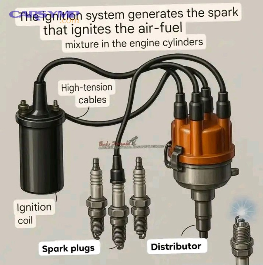
Spark testing represents the fundamental ignition diagnostic procedure. This test verifies whether high-voltage electricity reaches the spark plugs during cranking. WARNING: Ignition systems generate 30,000-50,000 volts capable of serious electrical shock. Never touch ignition wires, coils, or spark plugs while cranking or with the ignition on. Use insulated tools and maintain proper distance. To safely test for spark, remove a spark plug wire (on distributor systems) or disconnect a coil-on-plug connector and remove the coil (on coil-on-plug systems). Attach a spark tester—a specialized tool with a grounded metal probe and adjustable gap that simulates a spark plug—to the plug wire or coil. Ground the tester firmly to the engine block or cylinder head using a jumper wire or the tester’s grounding clip. Have an assistant crank the engine while you observe the spark tester from a safe distance.
A healthy ignition system produces bright blue-white spark that jumps the tester gap with consistent rhythm. Weak spark (yellow, orange, or thin blue) indicates insufficient coil output, high resistance in wiring, or poor ground connections. Intermittent spark (firing irregularly or missing pulses) suggests intermittent electrical problems, failing coil, or sensor signal issues. No spark at all confirms ignition system failure at that component—no high voltage is being generated or delivered.
Test multiple cylinders to determine failure scope. No spark at any cylinder indicates systemic failure—crankshaft position sensor not sending trigger signal, ignition module not commanding coil firing, or complete power supply loss to the ignition system. No spark at one cylinder (on coil-on-plug systems) indicates that specific coil has failed. Weak spark at all cylinders suggests general ignition weakness from low battery voltage, charging system problems, or failing ignition module affecting all coils equally.
Ignition coil resistance testing identifies failed coils without specialized equipment, requiring only a digital multimeter. Coils contain primary windings (typically 200-500 turns of heavier wire, low resistance) and secondary windings (15,000-30,000 turns of fine wire, high resistance). Measuring both resistances verifies coil integrity. Consult service information for your specific vehicle’s coil resistance specifications—values vary significantly by coil design.
To test primary resistance, remove the coil connector and measure resistance between the primary terminals (typically labeled + and – or B+ and signal). Typical primary resistance ranges from 0.5-2.0 ohms. Readings significantly higher indicate increased winding resistance from heat damage or corrosion; readings of infinite ohms (OL on multimeter) indicate open circuit—broken wire inside the coil. Significantly lower readings might indicate short-circuited windings, though this is less common.
Secondary resistance testing measures resistance from the primary negative terminal to the secondary output (the tower where the spark plug wire connects, or the spring terminal in coil-on-plug designs). Typical secondary resistance ranges from 6,000-15,000 ohms, depending on coil design. Infinite resistance indicates open secondary windings—the fine wire has broken internally, a common heat-related failure. Very low resistance might indicate shorted windings.
Resistance testing has limitations—it verifies electrical continuity but cannot detect heat-sensitive failures that only manifest when the coil reaches operating temperature. A coil may show correct resistance when cold (during testing) but fail when hot (during actual operation). This explains why intermittent heat-related stalling often passes shop testing conducted on cool engines.
Spark plug inspection reveals combustion conditions and potential ignition problems. Remove one or more spark plugs and examine the electrode and insulator condition. A properly functioning plug shows light tan or gray deposits on the insulator with minimal electrode wear. Specific conditions indicate problems:
- Black, sooty carbon deposits: Rich air-fuel mixture, excessive idling, or weak ignition allowing incomplete combustion
- White, blistered insulator: Overheating from lean mixture, over-advanced timing, or incorrect heat range plug
- Oil-fouled (wet, black, oily): Oil entering combustion chamber from worn rings, valve guides, or PCV system problems
- Melted electrodes: Severe overheating, detonation, or pre-ignition
- Worn, rounded electrodes: Normal wear after 60,000-100,000 miles requiring replacement
Measure spark plug gap with a wire-type feeler gauge. Gap should match specification (typically 0.028-0.060 inches, varying by vehicle). Excessive gap from electrode wear requires increased voltage to jump the gap, potentially exceeding coil output capacity and causing misfire or no-start. Insufficient gap reduces spark energy and may cause incomplete combustion.
Carbon tracking—visible carbon trails across the insulator from the terminal to the shell—indicates voltage is finding an easier path than jumping the electrode gap. This can cause misfire and is a common failure in plugs exposed to oil contamination or excessive moisture. Replace any plug showing carbon tracking.
Crankshaft position sensor testing requires scan tool capabilities or oscilloscope equipment. The scan tool method displays sensor data in real-time: Connect a capable scan tool (professional-level tools or some advanced consumer models), navigate to data display for crankshaft position sensor, and observe the RPM reading while cranking the engine. The sensor should show RPM rising smoothly and consistently. Erratic readings, intermittent signal loss (RPM drops to zero then returns), or complete absence of signal indicates sensor failure.
Oscilloscope testing provides more detailed analysis of the sensor’s AC voltage waveform. Magnetic crankshaft sensors generate AC voltage as reluctor teeth pass the sensor. The scope displays voltage amplitude and frequency, revealing weak signal strength, missing pulses, or erratic output. Hall-effect sensors produce digital square-wave signals that should show clean transitions between high and low voltage. Scope testing typically requires professional diagnostic equipment and interpretation skill.
Visual inspection sometimes reveals sensor problems: Check for metallic debris attached to the magnetic sensor tip (this creates resistance between sensor and reluctor, weakening signal). Inspect sensor connector for corrosion, bent pins, or backed-out terminals. Measure sensor-to-reluctor wheel air gap if adjustable (typically 0.020-0.050 inches specification)—excessive gap weakens signal. Some sensors are non-adjustable, with gap set by mounting location.
Sensor resistance testing verifies winding integrity in magnetic sensors. Typical specification is 200-1,000 ohms depending on sensor design. Infinite resistance indicates open windings; very low resistance might indicate short circuits. Hall-effect sensors cannot be resistance-tested as they contain solid-state electronics rather than simple windings.
Ignition module and ECM testing requires advanced diagnostic capability. These electronic control units receive sensor inputs (crankshaft position, camshaft position, engine load) and command ignition coil firing at precisely calculated timing. Modules fail from heat exposure, voltage spikes, or component aging. Testing involves verifying input signals reach the module (sensor signals, power supply, grounds), then confirming output signals command coils correctly. This typically requires professional scan tools capable of monitoring input/output signals in real-time or actuating outputs while monitoring results.
Following this diagnostic progression—spark testing first to confirm the problem is ignition-related, coil resistance testing to verify coil integrity, spark plug inspection for combustion condition evidence, sensor testing to verify trigger signals—systematically isolates ignition failures. Many ignition problems can be diagnosed with basic tools (multimeter, spark tester), though intermittent heat-related failures often require extended test drives with monitoring equipment or component replacement based on pattern recognition.
Which Ignition System Components Most Commonly Cause Stalling?
Crankshaft position sensors cause stalling most frequently among ignition components, followed closely by ignition coils, then spark plugs, ignition control modules, and finally wiring/connector issues. Understanding each component’s failure patterns and replacement costs helps prioritize diagnosis and repair decisions.
Crankshaft position sensors serve as the ignition system’s primary timing reference. The ECM cannot command proper ignition timing without accurate crankshaft position data. These sensors mount near the crankshaft or camshaft and detect rotating reluctor wheels or tone rings through magnetic induction (magnetic sensors) or optical/Hall-effect sensing (electronic sensors). The sensor generates signals indicating exactly where each piston is in its four-stroke cycle, enabling the ECM to fire the correct cylinder at the correct time.
Sensors fail from heat exposure due to their mounting location near the hot engine block. Internal windings in magnetic sensors develop insulation breakdown after years of heat cycling, creating intermittent short circuits that cause signal loss. Electronic components in Hall-effect sensors degrade with heat, producing weak or erratic signals. The characteristic failure pattern is temperature-related intermittent stalling—perfect operation when cold, intermittent stalling after reaching operating temperature, complete failure when critically overheated, recovery after cooling. This pattern so specifically indicates crankshaft sensor failure that many technicians replace the sensor based on symptom description alone, particularly on high-mileage vehicles (150,000+ miles).
External sensor damage also causes failure: Debris impact from road hazards can crack sensor housing, allowing moisture intrusion that corrodes internal components. Connector corrosion from road salt, water splash, or engine compartment moisture interrupts signal transmission. Mounting bolt loosening allows excessive air gap between sensor and reluctor, weakening signal strength below ECM recognition threshold.
Diagnosis combines symptom recognition (intermittent hot stalling with cool-down recovery), scan tool sensor monitoring (erratic or absent RPM signal during stalling events), and resistance testing (verify winding integrity). Sensors cannot be repaired—replacement is the only solution. Replacement sensors cost $40-150 depending on vehicle, with installation requiring 30-60 minutes labor ($75-150 labor cost). Total repair cost typically runs $125-300, making this one of the more affordable ignition system repairs. Given the high probability of sensor involvement in intermittent hot stalling and the reasonable replacement cost, many shops recommend sensor replacement as a first step rather than pursuing extended diagnosis.
Ignition coils transform battery voltage (12-14 volts) into the 30,000-50,000 volts required to jump the spark plug gap and ignite the air-fuel mixture. Modern coil-on-plug (COP) designs place individual coils directly atop each spark plug, eliminating spark plug wires and providing strong, reliable spark. These coils contain primary windings (connected to battery voltage and ECM control), secondary windings (high-voltage output), and internal electronics, all encapsulated in epoxy resin for insulation and moisture protection.
Coils fail primarily from heat cycling and vibration. Underhood temperatures reach 200-250°F during normal operation, even higher in turbo applications or during extended idle in traffic. The epoxy potting compound undergoes thermal expansion when heated and contraction when cooled. After thousands of heat cycles over 5-10 years, micro-cracks develop in the epoxy, allowing moisture intrusion and creating pathways for internal arcing between windings. When cool, cracks remain tight and insulation adequate; when heated, epoxy expands, cracks widen, arcing begins, and coil output drops or fails completely.
Failed coils produce cylinder-specific misfire codes (P0301-P0308) initially, as that coil’s cylinder fails to fire properly. If misfire is severe enough or the vehicle is a small-displacement engine (4-cylinder) where one dead cylinder represents 25% power loss, stalling may result. Heat-related failures create the hot-operation stalling pattern, though coil heat failure may occur at specific RPM ranges or loads rather than simply after time duration—the thermal stress varies with operating conditions.
Diagnosis involves resistance testing (described earlier), spark testing that cylinder, and often visual inspection for obvious cracks, carbon tracking on the coil exterior, or corrosion in the connector. Many scan tools can command specific coils to fire during testing, helping identify non-functional coils. Complete coil failure is definitive—no spark from that coil during testing, or OBD codes directly identifying that coil circuit. Marginal coils are more challenging, showing normal resistance when cool but failing under operating heat.
Replacement coils cost $75-200 each for OEM quality, with labor for coil-on-plug designs minimal (15-30 minutes per coil, $50-75 labor). Older distributor systems with single coils cost $100-300 for the coil assembly with similar labor. When one coil fails, technicians often recommend replacing all coils if the vehicle has high mileage (100,000+) and other coils are original, as they’ve experienced the same heat cycles and age-related degradation. Complete coil set replacement costs $400-800 parts plus $150-300 labor but prevents repeated repair visits as additional coils fail over subsequent months.
Spark plugs wear gradually through normal operation. Each spark across the plug gap erodes a tiny amount of electrode material. Over 60,000-100,000 miles (depending on plug design—copper-core plugs wear faster than platinum or iridium), electrodes become rounded and gap increases beyond specification. Larger gaps require higher voltage to jump, potentially exceeding coil output and causing misfire. Severely worn plugs may fail to fire at all under load (high cylinder pressure, cold conditions) even if they fire adequately at idle.
Fouling causes premature failure. Carbon deposits from rich running, excessive idling, or oil consumption coat the insulator and electrodes, providing conductive paths that short-circuit the plug rather than allowing spark across the gap. Oil fouling from worn piston rings or valve guides creates similar issues. Fuel contamination from additives or poor-quality gasoline can leave residues that foul plugs.
Plug inspection (described earlier in testing procedures) reveals condition. Replacement is straightforward: proper gap specification, correct heat range for the application, and tighten to torque specification (typically 15-25 ft-lbs). New plugs cost $5-20 each for standard copper, $15-40 each for platinum, and $20-50+ each for iridium long-life designs. A 4-cylinder engine requires 4 plugs ($20-200 parts depending on plug type); V6 requires 6 plugs ($30-300); V8 requires 8 plugs ($40-400). Labor varies dramatically by vehicle accessibility—easy engines (Honda 4-cylinder, many American V8s) take 30-60 minutes ($75-150 labor); difficult engines (Subaru boxer, some transverse V6s with rear cylinders under the firewall) can require 3-4 hours labor ($300-400) due to access requirements.
Ignition control modules/ECM failures represent less common but catastrophic failures. These electronic controllers receive sensor inputs and command coil firing. Failures produce sudden complete loss of spark to all cylinders (module failure) or specific cylinders (partial ECM failure). Heat-related failures mirror sensor and coil patterns. Voltage spikes from jump-starting, alternator failures, or other electrical system problems can damage sensitive electronics.
Diagnosis requires verifying sensor inputs reach the module correctly, then confirming module commands coil firing appropriately. This often requires professional-level scan tools with bi-directional control capability and oscilloscope analysis. Modules cannot be repaired—replacement is required. Standalone ignition modules (older vehicles) cost $100-300 with 1-2 hours labor. ECM replacement is expensive: $500-1,500 for remanufactured ECM, 2-3 hours labor for installation and programming ($200-300), total cost $700-1,800. Fortunately, ECM failures are significantly less common than sensors, coils, and plugs.
Wiring and connector problems create intermittent failures that mimic component failures. Corroded connector terminals increase resistance, reducing signal strength or creating open circuits. Vibration-loosened connectors intermittently lose contact. Chafed wiring from rubbing against sharp edges develops intermittent short circuits. Connector inspection should be part of any ignition diagnosis—clean, tight, corrosion-free connections are essential for proper ignition operation.
Understanding component failure frequency guides diagnostic priority: Intermittent hot stalling, check crankshaft sensor first. Cylinder-specific misfire causing stalling, replace that cylinder’s coil and spark plug. General weak spark, inspect plugs first (least expensive), then test coils. Complete no-spark, verify crankshaft sensor signal, then investigate module/ECM. This prioritization minimizes unnecessary parts replacement and diagnostic cost while addressing the most statistically probable failures first.
What Should You Do Once You’ve Identified the Problem System?
Once you’ve identified whether fuel or ignition system causes stalling, immediately prioritize repairs based on safety risk, component failure severity, and cost-effectiveness, starting with safety-critical items like sensors preventing restart, then addressing less severe issues like marginal components that allow limited operation. Specifically, the action plan should account for immediate drivability needs, repair budget constraints, and preventing secondary damage from continuing to operate with known failures.
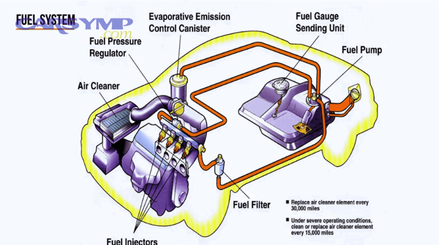
What Are the Typical Repair Costs for Fuel System vs Ignition System Stalling?
Fuel system stalling repairs range from $50-$150 for fuel filter replacement to $600-$1,200 for fuel pump replacement, while ignition system repairs cost $125-$300 for crankshaft position sensors, $150-$400 for spark plug replacement, and $400-$800 for complete ignition coil set replacement. Understanding these cost ranges helps prioritize repairs and budget appropriately, though actual costs vary by vehicle make, regional labor rates, and parts quality selection.
The following table provides a Repair cost estimate for common stall causes across both systems:
| Component | Parts Cost | Labor Cost (hours) | Total Typical Cost | Failure Frequency | Repair Priority |
|---|---|---|---|---|---|
| Fuel System Repairs | |||||
| Fuel Filter | $15-$50 | 0.3-0.5 ($40-$75) | $55-$125 | High | High – Preventive |
| Fuel Pressure Regulator | $80-$250 | 0.5-1.0 ($75-$150) | $155-$400 | Medium | Medium |
| Single Fuel Injector | $50-$150 | 1.0-2.0 ($100-$300) | $150-$450 | Medium | Medium |
| Complete Injector Set (4-cyl) | $200-$600 | 2.0-3.0 ($200-$450) | $400-$1,050 | Low | Low – Only if multiple fail |
| Fuel Pump (accessible) | $150-$400 | 1.0-2.0 ($100-$300) | $250-$700 | High | High |
| Fuel Pump (in-tank) | $200-$800 | 3.0-5.0 ($300-$750) | $500-$1,550 | High | High |
| Ignition System Repairs | |||||
| Spark Plugs (4-cyl, standard) | $20-$80 | 0.5-1.0 ($75-$150) | $95-$230 | Medium | High – Preventive |
| Spark Plugs (V6, standard access) | $30-$120 | 1.0-1.5 ($100-$225) | $130-$345 | Medium | High – Preventive |
| Spark Plugs (difficult access) | $30-$120 | 3.0-4.0 ($300-$600) | $330-$720 | Medium | Medium |
| Single Ignition Coil | $75-$200 | 0.3-0.5 ($50-$75) | $125-$275 | High | High |
| Complete Coil Set (4-cyl) | $300-$800 | 1.0-2.0 ($100-$300) | $400-$1,100 | Medium | Medium – If multiple failing |
| Crankshaft Position Sensor | $40-$150 | 0.5-1.5 ($75-$225) | $115-$375 | Very High | Very High |
| Camshaft Position Sensor | $45-$160 | 0.5-1.0 ($75-$150) | $120-$310 | Medium | High |
| Ignition Control Module | $100-$300 | 1.0-2.0 ($100-$300) | $200-$600 | Low | Medium |
Several factors influence actual repair costs beyond base component and labor estimates. Vehicle make significantly affects parts costs—luxury European vehicles (BMW, Mercedes-Benz, Audi) typically cost 50-150% more for parts than domestic or Asian brands due to proprietary parts and limited aftermarket availability. Labor rates vary by region and shop type: independent shops typically charge $75-$125 per hour, while dealership labor runs $125-$175+ per hour in metropolitan areas. Parts quality selection also impacts cost: Original Equipment Manufacturer (OEM) parts cost 20-50% more than quality aftermarket equivalents but may include better warranty coverage and guaranteed fit.
Diagnostic fees add to repair costs. Many shops charge diagnostic time separately from repair labor—typically 1.0-2.0 hours ($100-$300) to identify the specific component failure. Some shops waive diagnostic fees if the customer authorizes repairs, while others charge diagnostics separately regardless. Mobile diagnostic services may charge travel fees in addition to diagnostic time. Complex intermittent problems requiring extended test drives or multiple diagnostic sessions can accumulate significant diagnostic costs before identifying the failure.
Warranty coverage significantly impacts out-of-pocket costs. Powertrain warranties typically cover engine components including fuel pumps, sensors, and ignition systems for 5 years/60,000 miles (basic coverage) or 10 years/100,000 miles (extended powertrain). Extended warranties purchased separately vary widely in coverage—some exclude wear items like spark plugs while covering sensors and pumps; others provide comprehensive coverage. Verify warranty coverage before authorizing repairs, as warranty claims require using authorized repair facilities and specific parts.
The cost comparison between fuel and ignition system repairs generally favors ignition system repairs as more affordable for common failures. Crankshaft sensor replacement ($115-$375) costs significantly less than fuel pump replacement ($500-$1,550 for in-tank pumps), making misdiagnosis expensive. This emphasizes the importance of accurate stalling diagnosis before committing to repairs. Spark plug replacement, while varying widely based on vehicle ($95-$720), represents routine maintenance that often resolves stalling at reasonable cost. Fuel filter replacement offers similar preventive value at low cost ($55-$125).
Prioritize repairs based on safety and cost-effectiveness. Address complete failures preventing vehicle operation first: crankshaft sensor showing no signal, fuel pump producing no pressure, or completely failed ignition coils. These failures create safety risks from unexpected stalling in traffic and total loss of transportation. Second priority includes marginal components causing intermittent stalling: heat-sensitive sensors and coils, weak fuel pumps, or severely worn spark plugs. These allow limited operation but risk progressive failure and potential secondary damage. Third priority addresses preventive maintenance items like fuel filters and spark plugs approaching service intervals—these may not currently cause stalling but prevent future failures at low cost.
Consider repair value versus vehicle value. If a high-mileage vehicle (200,000+ miles) worth $3,000 requires $1,500 in fuel pump replacement, evaluate whether the repair makes economic sense or if investing that money toward replacement vehicle purchase provides better value. Conversely, newer vehicles under warranty should always have stalling issues properly diagnosed and repaired under coverage to prevent progressive damage.
Should You DIY or Seek Professional Help?
DIY repairs are appropriate for accessible components with straightforward replacement procedures like external fuel filters, spark plugs in easily-accessed engines, and ignition coils in coil-on-plug systems, while professional service is necessary for in-tank fuel pumps, complex diagnostic procedures requiring specialized scan tools, and repairs on vehicles with active warranties. More specifically, the decision depends on tool availability, mechanical skill level, safety considerations, and time constraints.
Several fuel and ignition system repairs are well-suited to DIY completion by mechanically-inclined vehicle owners with basic tools. Fuel filter replacement on vehicles with accessible external filters requires minimal tools (wrenches, fuel line disconnect tools, catch pan) and follows straightforward procedures: relieve fuel system pressure, disconnect fuel lines using quick-disconnect tools, remove old filter noting flow direction arrow, install new filter matching arrow orientation, reconnect lines, and verify no leaks. Total time: 20-40 minutes. Difficulty level: Easy. Cost savings: $40-75 in labor charges. Safety considerations: Work in ventilated area, have fire extinguisher available, relieve system pressure before disconnecting lines, avoid open flames or smoking near fuel.
Spark plug replacement suits DIY when plugs are readily accessible. Four-cylinder engines with plugs accessible from above the engine and V-configuration engines with easily removable intake components or coil covers allow straightforward plug access. Required tools: spark plug socket (5/8″ or 16mm typically), ratchet and extension, gap gauge, anti-seize compound, dielectric grease. Procedure: Remove ignition coils or plug wires one at a time, use compressed air to blow debris from plug well, remove old plug, verify new plug gap, apply anti-seize to threads (sparingly—only 1-2 threads), install new plug finger-tight then torque to specification (typically 15-25 ft-lbs), reinstall coil or wire. Total time: 30-90 minutes depending on cylinder count and accessibility. Difficulty: Easy to moderate. Cost savings: $75-400 in labor. Critical success factors: Correct torque (over-tightening damages threads, under-tightening allows loosening and heat damage), proper gap setting, maintaining spark plug wire/coil-to-cylinder assignments.
Ignition coil replacement in coil-on-plug systems represents another DIY-friendly repair. Individual coils mount atop spark plugs with single bolt retention and electrical connector. Tools needed: 10mm or 8mm socket (typically), ratchet, dielectric grease. Procedure: Disconnect battery negative terminal, remove coil mounting bolt, disconnect electrical connector, pull coil from spark plug (may require gentle twisting if stuck), apply dielectric grease to inside coil boot, install new coil, reconnect connector, install mounting bolt. Time per coil: 10-15 minutes. Difficulty: Easy. Cost savings: $50-75 labor per coil. Note: Some vehicles require removing intake components or other parts to access rear cylinders, increasing difficulty and time.
Crankshaft position sensor replacement ranges from simple to complex depending on sensor location. Sensors mounted on the front timing cover with clear access allow straightforward DIY replacement: disconnect battery, locate sensor, disconnect electrical connector, remove mounting bolt, extract sensor, install new sensor verifying proper air gap if adjustable, reconnect, and test. Time: 20-40 minutes. Difficulty: Easy to moderate. However, sensors mounted behind timing covers, under exhaust manifolds, or in transmission bell housings require extensive disassembly and are better suited to professional service.
Fuel pressure testing can be performed DIY with rented or purchased fuel pressure gauge kit ($30-80 purchase, often free rental from auto parts stores with deposit). Procedures described earlier in testing sections allow verification of fuel system pressure without professional equipment. This DIY diagnostic capability can confirm or eliminate fuel pump/filter issues before committing to professional diagnosis.
However, several repairs definitely require professional service due to complexity, specialized tools, or safety concerns. In-tank fuel pump replacement requires draining the fuel tank (hazardous without proper fuel storage containers and ventilation), supporting the vehicle securely on lifts or jack stands, disconnecting fuel lines and electrical connections, removing tank mounting straps, lowering the tank, accessing the pump module, and reversing for installation. Specialized tools often include fuel line disconnect tools for specific manufacturers, tank strap wrenches, and fuel transfer pumps. Safety requirements are substantial: work area must be well-ventilated with no ignition sources, fuel must be properly stored and handled, electrical connections must be made correctly to prevent fire risk. This repair is best left to professionals with proper facilities, even for experienced DIYers. Professional cost ($500-1,550) includes safe fuel handling, proper disposal, and warranty on work.
Advanced diagnostics requiring professional scan tools exceed DIY capability for most owners. While consumer-level OBD-II scanners ($30-300) can read and clear basic diagnostic trouble codes, they cannot perform the advanced functions needed for comprehensive stalling diagnosis: monitoring sensor data in real-time during test drives, commanding actuators for verification testing, reading proprietary manufacturer codes beyond generic OBD-II, graphing sensor data for pattern analysis, or performing bidirectional control tests. Professional shops invest $5,000-$10,000 in diagnostic scan tools with these capabilities. For intermittent stalling requiring extended diagnosis with monitoring equipment, professional diagnostic service ($100-300 for diagnostic time) provides value through specialized equipment access and diagnostic expertise.
Fuel injector service and testing requires specialized equipment most DIYers don’t possess. While injector replacement is mechanically straightforward (disconnect fuel rail, remove injectors, install new injectors with new O-rings, reinstall fuel rail), verifying that injectors actually need replacement versus just cleaning requires flow testing and spray pattern analysis using specialized injector test benches. Professional shops can perform ultrasonic injector cleaning ($150-300 for set of 4-8 injectors) that restores function without replacement cost. The equipment investment for injector cleaning ($3,000-8,000 for quality ultrasonic cleaners and test equipment) makes this a clear professional-service item.
Vehicles under active warranty—factory warranty or purchased extended warranty—should always be serviced professionally at authorized facilities. Warranty terms typically require repairs be performed by licensed technicians using approved parts and procedures. DIY repairs often void warranty coverage even for unrelated future failures under the “modified vehicle” exclusion. The warranty value (potentially $1,000-5,000 of covered repairs over the warranty period) far exceeds DIY labor savings ($100-300 per repair), making professional service the clear choice for warranted vehicles.
Consider professional service when any of these factors apply: Lack of appropriate tools (torque wrench, scan tool, specialized sockets), insufficient mechanical experience (first-time major repair attempt), time constraints (need vehicle operational quickly), safety concerns (working with high-voltage ignition systems or pressurized flammable fuel), or complex diagnostics (intermittent problems requiring systematic testing). Professional technicians complete repairs faster through experience and tool availability, provide warranties on work performed (typically 1-3 years/12,000-36,000 miles), and maintain insurance covering damage from repair errors.
DIY when: Component is accessible, procedure is straightforward, you possess necessary tools and skills, time is available, and safety can be maintained. Professional service when: Component access is difficult, specialized tools are required, diagnosis is complex, safety risks are high, warranty coverage exists, or time/convenience value exceeds labor cost savings. Making informed DIY-versus-professional decisions maximizes value while ensuring safe, effective stalling repairs.
How Can You Prevent Fuel and Ignition System Stalling Before It Happens?
Preventing fuel and ignition system stalling requires following manufacturer-recommended maintenance schedules including fuel filter replacement every 30,000-50,000 miles, spark plug replacement every 60,000-100,000 miles, and using quality fuel from reputable stations, combined with addressing check engine lights and diagnostic codes promptly before component degradation causes complete failure. Let’s examine specific preventive measures for each system.
What Is the Recommended Maintenance Schedule for Fuel System Components?
Fuel system preventive maintenance centers on three key components—fuel filter, fuel injectors, and fuel pump—each with specific service intervals and procedures that prevent the gradual degradation leading to stalling.
Fuel filter replacement represents the single most important fuel system preventive maintenance. Filters accumulate contaminants from fuel tank corrosion, debris in gasoline, and breakdown products from fuel system components. Filter capacity gradually depletes until restriction becomes severe enough to limit fuel flow. Manufacturers typically specify fuel filter replacement intervals of 30,000-50,000 miles for vehicles with external serviceable filters. Some modern vehicles use lifetime filters integrated with the in-tank fuel pump module, which theoretically don’t require replacement but in practice may benefit from service after 100,000-150,000 miles if fuel delivery issues arise.
Replacement timing should account for fuel quality and operating conditions. Vehicles consistently fueled at questionable stations (small rural stations with potentially old fuel, contaminated underground tanks) benefit from more frequent filter service—every 20,000-30,000 miles. Diesel vehicles require more frequent filter attention due to biological growth in diesel fuel and wax formation in cold weather. Vehicles operating in dusty environments (construction sites, unpaved roads) may experience faster filter loading from airborne particulates entering the fuel system through tank venting systems.
Filter replacement procedure (described earlier for DIY) is straightforward and inexpensive ($55-125 total cost), making this exceptional preventive value. A $50 filter replacement every 40,000 miles prevents the $600-1,200 fuel pump replacement that might result from pump overworking against severe restriction, providing 10:1 or better return on preventive investment.
Fuel injector cleaning prevents the gradual carbon and varnish buildup that restricts injector spray orifices and disrupts spray patterns. Modern gasoline contains detergent additives designed to clean injectors during normal operation, and these “top tier” fuels from major brands (Shell, Chevron, BP, Mobil, etc.) provide adequate cleaning for most vehicles. However, injectors operating in engines with excessive carbon buildup (from extended idling, frequent short trips, poor-quality oil allowing blow-by), high-mileage vehicles (100,000+ miles), or those using low-quality fuel without adequate detergents benefit from periodic professional cleaning.
Professional fuel injector cleaning service involves introducing concentrated detergent cleaners into the fuel system while the engine runs, allowing the cleaning chemicals to dissolve deposits through the injectors and combustion chambers. This service costs $100-200 and is typically recommended every 30,000-50,000 miles on high-mileage vehicles or when symptoms suggest injector restriction—rough idle, decreased fuel economy, loss of power. Over-the-counter fuel injector cleaners added to the gas tank ($8-15 per bottle, used every 3,000-5,000 miles) provide maintenance-level cleaning between professional services but cannot address severe deposits.
Ultrasonic injector cleaning ($150-300 for removal, ultrasonic cleaning, flow testing, and reinstallation) represents the highest level of injector service, removing severe deposits that resist chemical cleaning. This service suits high-mileage vehicles (150,000+ miles) with original injectors showing symptoms of severe restriction or when chemical cleaning fails to resolve injector-related issues.
Fuel pump longevity correlates strongly with maintaining adequate fuel level in the tank. Pumps are cooled and lubricated by the gasoline they’re submerged in. Running the tank below 1/4 full regularly exposes the pump to air, reducing cooling effectiveness and accelerating wear. Heat buildup damages pump motor commutator and brushes, shortening pump life. Additionally, fuel tanks with low levels allow sediment settled at tank bottom to be drawn into the pump, potentially clogging the internal pump filter (separate from the main fuel filter) and accelerating wear.
Best practice: maintain fuel level above 1/4 tank, particularly in hot weather when fuel temperatures rise and cooling becomes more critical. This simple operational habit can extend fuel pump life from the typical 100,000-150,000 miles to 200,000+ miles. Given pump replacement costs ($500-1,550), the value of this preventive measure is substantial.
Fuel quality matters significantly for system longevity. Major-brand top-tier gasoline contains enhanced detergent packages that prevent injector deposits, keep intake valves clean, and reduce combustion chamber carbon—all factors that indirectly affect fuel system performance. While top-tier fuel costs $0.05-0.15 more per gallon than budget brands, the $2-6 extra cost per tank provides value through reduced maintenance needs and optimized fuel efficiency. Conversely, consistently using the cheapest available fuel—often from small independent stations with potentially contaminated or old fuel—increases risk of fuel system problems from poor detergent content, water contamination, or biological growth in diesel fuel.
Avoid fuel additives making dramatic performance claims—”gain 20 horsepower,” “clean your engine in one tank”—as these often contain harsh solvents that may damage fuel system seals and O-rings. Stick with reputable cleaner brands (Chevron Techron, BG 44K, Sea Foam) used at recommended dilutions and intervals.
Monitor fuel system performance indicators as preventive maintenance cues. Gradually declining fuel economy without explanation may indicate injector deposits or restricted fuel filter reducing combustion efficiency. Extended cranking time before engine starts suggests fuel pressure leak-down from weak pump check valve or leaking injectors—addressing this early prevents complete pump failure. Rough idle or hesitation during acceleration hints at injector problems or marginal fuel delivery that benefits from cleaning before restriction becomes severe enough to cause stalling.
What Is the Recommended Maintenance Schedule for Ignition System Components?
Ignition system preventive maintenance focuses on spark plugs as the primary wear item, with attention to ignition coils and sensors as needed based on mileage, operating conditions, and symptom development.
Spark plug replacement intervals vary dramatically based on plug design. Traditional copper-core plugs require replacement every 30,000-40,000 miles due to rapid electrode wear. Platinum-tip plugs extend life to 60,000-80,000 miles through more wear-resistant electrode material. Iridium plugs offer the longest life, typically 80,000-120,000 miles, with some manufacturers specifying 100,000+ mile intervals. Always follow manufacturer specifications for plug type and replacement interval—using long-life plugs doesn’t justify extending replacement intervals beyond specification, as plug gap increases with wear regardless of electrode material.
Replacement timing should account for operating conditions. Engines experiencing heavy loads (towing, commercial use, performance driving) create more electrode erosion and benefit from replacement at the lower end of the service interval. Vehicles operated primarily in short-trip service (frequent cold starts, limited highway operation) may experience fouling before reaching the full service interval, particularly in older engines with some oil consumption. Inspect plugs at 50-60% of their rated life (around 40,000-50,000 miles for 100,000-mile plugs) to verify condition and identify developing problems before they cause stalling.
Spark plug replacement cost ($95-720 depending on accessibility, as detailed earlier) provides substantial value as preventive maintenance. New plugs restore full ignition energy, improving fuel efficiency by 2-5% through more complete combustion, reducing emissions, improving engine performance, and most importantly, preventing the misfire-related stalling that occurs when worn plugs can no longer reliably fire under load. The fuel savings alone often offset plug replacement cost over the remaining plug life.
Ignition coil replacement follows condition-based rather than interval-based maintenance. Coils don’t wear in the traditional sense—they either function correctly or they fail, typically without a gradual degradation period that allows preventive replacement. However, coils on high-mileage vehicles (100,000+ miles) experiencing multiple coil failures benefit from complete set replacement to prevent repeated repair visits. As discussed earlier, replacing all coils when one fails eliminates the frustration of addressing individual coil failures every few months as additional coils reach end-of-life.
Monitor for early coil failure indicators: rough idle that worsens when wet (moisture exposure reveals marginal coil insulation), misfire codes appearing after extended highway driving (heat-sensitive coil degradation), or engine performance degradation during hard acceleration or high load (coil cannot deliver full output under stress). Addressing these early symptoms through coil replacement prevents the eventual stalling that occurs when misfire becomes severe enough to prevent sustained operation.
Crankshaft position sensors similarly follow condition-based replacement. These sensors typically last 150,000-200,000 miles without issue, but failures can occur earlier, particularly in harsh operating environments (extreme heat, severe vibration, water exposure in flood-prone areas). The intermittent hot-stalling pattern described earlier provides clear indication for sensor replacement. Given the relatively low cost ($115-375) and high consequence of failure (stalling in traffic, stranded condition), many technicians recommend preemptive sensor replacement on vehicles approaching 150,000 miles showing any intermittent stalling symptoms, even without confirmed diagnosis. The peace of mind and prevention of roadside breakdown often justifies the preemptive replacement.
Battery and charging system maintenance prevents ignition system problems indirectly. Weak batteries provide insufficient voltage for full coil output, creating weak spark that contributes to misfire and stalling, particularly at idle when alternator output is minimal. Failing alternators produce low or unstable voltage affecting ECM and ignition module operation. Battery testing (load test, voltage test) and alternator testing (output test, ripple test) should occur during regular service intervals—every oil change or at minimum annually. Batteries typically last 3-5 years; replacement before complete failure prevents the voltage-related ignition problems that occur with marginal batteries.
Connector and wiring inspection prevents electrical failures that mimic component failures. Annually inspect visible ignition system connectors for corrosion, loose retention, or physical damage. Apply dielectric grease to coil boot connections during spark plug service to prevent moisture intrusion and corrosion. Check ground connections—clean, tight grounds are essential for proper ignition operation. These simple inspections during routine maintenance prevent the majority of wiring-related ignition failures.
Operating habits affect ignition system longevity. Avoid extended cranking attempts (more than 10-15 seconds continuously) when the engine won’t start—this generates extreme heat in the starter and ignition system without cooling airflow, potentially damaging coils and modules. If the engine doesn’t start after 15 seconds, wait 30-60 seconds for components to cool before attempting another start cycle. Excessive idling generates heat without the cooling airflow of driving, accelerating coil degradation—modern engines warm quickly and don’t require extended idle warm-up periods.
Monitor check engine lights and address diagnostic codes promptly. Misfire codes (P0300-P0308) indicate developing ignition or fuel problems requiring attention before they progress to stalling-level severity. Addressing a single-cylinder misfire code by replacing that cylinder’s coil and spark plug (total cost $150-300) prevents the eventual multi-cylinder misfire that causes stalling and potentially damages the catalytic converter (replacement cost $800-2,500) through excessive unburned fuel passage. Early intervention based on code appearance represents cost-effective preventive maintenance.
Can Both Systems Fail Simultaneously and Cause Stalling?
Yes, fuel and ignition systems can fail simultaneously, though this typically occurs through related electrical system problems affecting both systems rather than independent coincidental failures, creating diagnostic challenges that require systematic testing to identify all contributing failures. Specifically, electrical system degradation, computer malfunctions, and sensor failures that feed both systems represent the primary scenarios where simultaneous failures occur.
Electrical system problems affecting both fuel and ignition systems commonly stem from charging system failures or major ground connection issues. When the alternator fails completely while driving, battery voltage begins declining as the battery supplies all electrical loads without recharging. As voltage drops from the normal 13.8-14.4 volts down to 11-10 volts, multiple effects occur: Ignition coils require minimum voltage (typically 11-12 volts) to generate full output—low voltage produces weak spark leading to misfire. Fuel pump motors slow as voltage drops, reducing pressure and flow. The ECM may enter reduced-function mode or fail to operate correctly at low voltage, disrupting both fuel injection commands and ignition timing control. The result is simultaneous fuel delivery degradation and ignition system weakness, both contributing to rough running and eventual stalling.
This scenario creates diagnostic confusion because the mechanic sees evidence of both fuel system problems (low pressure, lean mixture codes) and ignition system problems (misfire codes, weak spark) and might misdiagnose as needing both fuel pump and ignition coils when the root cause is actually the alternator. Proper diagnosis requires testing charging system voltage and function before condemning fuel or ignition components. A simple voltage test during operation reveals charging system failure, directing repair to the alternator ($400-800 typical cost) rather than unnecessary fuel and ignition component replacement.
Major ground connection failures produce similar effects. The engine block serves as the ground return path for ignition coils, fuel injectors, sensors, and other electrical components. If the primary ground strap connecting engine to chassis or battery negative becomes corroded, loose, or broken, all electrical circuits using that ground path experience increased resistance and voltage drop. The symptoms mirror low-voltage conditions: weak ignition spark, reduced fuel injector pulse strength, sensor signal degradation, and ECM malfunction. Multiple diagnostic codes may appear (misfire codes, sensor codes, fuel system codes) suggesting complex failures when the actual problem is a single failed ground connection.
Ground inspection should be standard practice during stalling diagnosis. Locate primary ground straps (typically 1-2 braided cables connecting engine to chassis near the transmission or on the engine block), verify tight bolt connections at both ends, inspect for corrosion (green or white crusty deposits), and test continuity with a multimeter (should show less than 0.1 ohms resistance from engine block to battery negative terminal). Clean and tighten ground connections as preventive maintenance during any electrical system service.
ECM and PCM (Powertrain Control Module) failures can simultaneously affect fuel and ignition because these computers control both systems. The ECM commands fuel injector pulse width and duration while also commanding ignition coil firing timing. Internal ECM failures—failed circuit boards from heat or vibration, corrupted software, or voltage spike damage—may affect output driver circuits controlling both systems. The result is loss of fuel injection signals to one or more cylinders and simultaneous loss of ignition signals, creating a condition where the engine lacks both fuel and spark.
ECM diagnostics require professional-level equipment to monitor input and output signals. If sensor inputs are normal but output commands are absent or incorrect, ECM failure is indicated. Replacement represents expensive repair ($700-1,800 as detailed earlier), but attempting to repair fuel and ignition component by component when the root cause is ECM failure wastes money on unnecessary parts. This emphasizes the value of comprehensive diagnosis before parts replacement.
Shared sensor failures can create cascading effects in both systems. The crankshaft position sensor provides the critical timing reference for both fuel injection and ignition spark—the ECM needs to know piston position to inject fuel at the correct time and fire spark at the correct moment. Complete sensor failure simultaneously eliminates both fuel injection and ignition, creating a no-start condition. Intermittent sensor problems may cause irregular fuel injection timing and erratic ignition timing, both contributing to rough running and stalling.
The mass airflow (MAF) sensor or manifold absolute pressure (MAP) sensor tells the ECM how much air is entering the engine, which determines both fuel quantity needed and optimal ignition timing for that load. A failed MAF sensor reporting incorrect airflow causes the ECM to command wrong fuel quantity (rich or lean mixture) and may cause inappropriate ignition timing, both degrading combustion and potentially causing stalling. This represents a single component failure creating dual-system effects through incorrect ECM calculations.
Contaminated fuel represents another scenario where one problem affects both systems. Water contamination in the fuel tank passes through the fuel system into cylinders. The fuel system delivers water instead of fuel (fuel starvation effect), while the ignition system attempts to ignite a non-flammable water-fuel mixture (combustion failure effect). The result is stalling from both inadequate fuel and inability to ignite what’s delivered. Symptoms include rough running, white exhaust smoke (steam), and difficulty starting. Diagnosis involves fuel sample inspection for water presence—fuel and water don’t mix and visibly separate in a clear container. Repair requires draining the fuel tank, replacing the fuel filter, and filling with fresh fuel ($200-400 typical cost for tank drain service).
Timing belt or chain failures affect both systems mechanically rather than electrically. The timing belt/chain synchronizes crankshaft and camshaft rotation, ensuring valves open and close at the correct points in the four-stroke cycle. Belt/chain failure allows camshafts to stop rotating while the crankshaft continues (in non-interference engines) or causes catastrophic valve-piston collision (in interference engines). Without camshaft rotation, intake valves don’t open (no air enters, no fuel can be drawn in—fuel system effect) and valve overlap periods that assist exhaust scavenging don’t occur (combustion efficiency degradation—ignition system effect). The engine cannot run because both air-fuel mixture delivery and combustion chamber preparation fail simultaneously. Prevention involves following timing belt replacement intervals (typically 60,000-100,000 miles depending on engine design) and monitoring for timing chain noise indicating wear.
Diagnosing simultaneous failures requires systematic approach: Test charging system and grounds first—these affect everything and are simple to verify. Check for shared sensor failures—crankshaft sensor, MAF sensor, ECT sensor—that influence both fuel and ignition calculations. Verify ECM operation through comprehensive scan tool testing before replacing multiple components. Inspect for obvious contamination (water in fuel, massive vacuum leaks). Only after eliminating systemic and shared failures should diagnosis proceed to individual component-level testing of fuel and ignition parts. This prevents the expensive mistake of replacing fuel pumps and ignition coils when the actual problem is a $150 crankshaft sensor or a $30 corroded ground strap.
What Role Do Sensors Play in Both Fuel and Ignition System Stalling?
Sensors provide critical input data enabling the ECM to calculate optimal fuel delivery quantity and ignition timing, with crankshaft position sensors controlling timing reference, mass airflow or MAP sensors determining load for fuel quantity, oxygen sensors providing feedback for mixture correction, and coolant temperature sensors adjusting enrichment for engine temperature—failures in any of these sensors can cause fuel delivery errors, ignition timing problems, or both, leading to stalling. Let’s examine each sensor’s role and failure effects.
Crankshaft position sensors (CKP) serve as the ignition system’s primary timing reference and the fuel injection system’s injection timing trigger. The sensor monitors crankshaft rotation speed and position, generating signals that tell the ECM exactly where each piston is in its four-stroke cycle. For ignition timing, the ECM uses CKP data to command spark at the precise crankshaft degree specified for optimal combustion—typically 10-20 degrees before top dead center (BTDC) at idle, advancing with engine speed and load. For fuel injection, the ECM uses CKP data to trigger injector firing at the correct time to ensure fuel spray enters the cylinder when the intake valve is open.
CKP sensor failures create catastrophic effects because the ECM loses all timing reference. Without knowing where the crankshaft is, the ECM cannot command ignition or injection—both systems shut down completely, causing immediate stalling and preventing restart until the sensor recovers (intermittent failure) or is replaced (permanent failure). The critical nature of this sensor explains why intermittent CKP sensor problems rank as the number one cause of mysterious intermittent stalling—when the sensor fails, everything stops instantly; when it recovers, everything resumes normally, often without setting diagnostic codes that survive the recovery event.
Camshaft position sensors (CMP) provide cylinder identification in sequential fuel injection systems and variable valve timing feedback. While the crankshaft sensor indicates piston position, it cannot distinguish which cylinder is on the compression stroke versus exhaust stroke (in a 4-cylinder engine, two pistons reach TDC simultaneously—one on compression, one on exhaust). The camshaft sensor provides this identification, allowing sequential injection where each injector fires individually at the optimal time rather than batch firing where all injectors pulse together. CMP sensor failure typically causes the ECM to revert to batch-fire injection mode and non-optimal ignition timing, creating rough running and potential stalling rather than complete failure like CKP sensor loss.
Mass airflow (MAF) sensors measure incoming air mass, providing the fundamental data for fuel quantity calculation. The ECM needs to know how much air is entering to calculate the correct fuel quantity for stoichiometric combustion (approximately 14.7:1 air-fuel ratio for gasoline). The MAF sensor contains a heated wire or film element—incoming air cools the element, requiring increased electrical current to maintain target temperature. This current measurement correlates directly to air mass flow. The ECM calculates fuel injector pulse width based primarily on MAF sensor data.
MAF sensor contamination from oil residue (from over-oiled aftermarket air filters) or dust creates the most common failure mode. Contamination insulates the sensing element, reducing heat transfer and causing incorrect readings—typically reading lower than actual airflow. The ECM delivers less fuel than needed based on these incorrect readings, creating lean conditions that cause rough running, hesitation, and potential stalling, particularly at idle where airflow is minimal and sensor accuracy is critical. Ignition timing is also affected because the ECM uses load calculation (based on MAF data) to determine timing advance—incorrect load reading causes suboptimal timing that reduces power and efficiency.
MAF sensor cleaning with specialized MAF cleaner spray ($8-12) often restores function without sensor replacement. Gently spray the sensing element (don’t touch with anything solid—elements are extremely fragile) and allow to dry completely before reinstalling. If cleaning doesn’t resolve symptoms, replacement sensors cost $150-400 depending on vehicle.
Manifold absolute pressure (MAP) sensors serve similar functions to MAF sensors on speed-density fuel injection systems (systems without MAF sensors). MAP sensors measure intake manifold vacuum/pressure, which correlates with engine load—high vacuum (low pressure, like 10-15 in-Hg) indicates light load or deceleration, while low vacuum (high pressure, approaching atmospheric 14.7 PSI) indicates heavy load or wide-open throttle. The ECM calculates air mass entering cylinders based on MAP reading, engine speed, and temperature, then computes required fuel quantity.
MAP sensor failures cause similar lean or rich conditions depending on failure mode. A sensor reading high pressure (low vacuum) when actual vacuum is high causes the ECM to deliver excessive fuel (rich condition, black smoke, poor economy, possible flooding and stalling). Conversely, a sensor reading low pressure when vacuum is high causes lean conditions (hesitation, misfire, potential stalling). MAP sensors include vacuum hose connections that can develop leaks or restrictions affecting readings—inspect vacuum hose condition during any MAP-related diagnosis. Replacement sensors cost $80-250.
Oxygen sensors (O2 sensors) provide feedback about combustion efficiency by measuring oxygen content in exhaust gases. Stoichiometric combustion (ideal air-fuel ratio) produces exhaust with minimal excess oxygen. Rich mixtures (excess fuel) produce exhaust with very low oxygen content; lean mixtures (excess air) produce exhaust with high oxygen content. The ECM uses O2 sensor voltage signals (rich mixture = high voltage around 0.8-1.0V, lean mixture = low voltage around 0.1-0.3V) to trim fuel delivery for optimal efficiency.
O2 sensor failures prevent closed-loop fuel control, forcing the ECM into open-loop operation using preset fuel maps without feedback correction. This can cause rich or lean conditions depending on the specific failure mode and baseline programming. Failed sensors typically don’t cause immediate stalling but create conditions contributing to stalling over time—rich conditions foul spark plugs, lean conditions cause hesitation and misfire. Modern vehicles have upstream O2 sensors (before catalytic converter) for fuel control and downstream sensors (after converter) for catalyst monitoring. Upstream sensor failures affect fuel delivery; downstream sensor failures typically only trigger check engine lights without driveability impact.
O2 sensors wear gradually, losing response speed and accuracy after 60,000-100,000 miles. Replacement represents maintenance rather than repair. Sensors cost $60-200 each; most vehicles have 2-4 sensors. Replace upstream sensors when exhibiting slow response on scan tool data monitoring or when diagnosed as cause of fuel control problems.
Engine coolant temperature (ECT) sensors tell the ECM current engine temperature, enabling temperature-based fuel and ignition adjustments. Cold engines require rich fuel mixture (excess fuel compensates for poor atomization and cylinder wall condensation), reduced ignition timing advance (cold dense air mixture burns faster requiring less advance), and elevated idle speed (additional airflow overcomes cold oil resistance). The ECT sensor is typically a thermistor—electrical resistance decreases as temperature increases—mounted in the coolant passage. The ECM measures voltage across the thermistor to determine temperature.
ECT sensor failures cause inappropriate fuel enrichment and ignition timing for actual temperature. A sensor stuck reading cold (high resistance) causes constant over-enrichment and retarded timing, creating black exhaust smoke, spark plug fouling, poor fuel economy, and potential flooding that prevents starting or causes stalling. A sensor stuck reading hot (low resistance) causes lean mixture when actually cold, creating difficult cold starting, stalling when cold, and rough running until the engine genuinely reaches operating temperature. Failed ECT sensors typically set diagnostic codes (P0115-P0119 range) helping identify the problem.
Replacement ECT sensors are inexpensive ($20-60) and usually easily accessible near the thermostat housing or in the cylinder head. The critical aspect is properly filling and bleeding the cooling system after replacement to prevent air pockets that cause overheating. DIY-capable for mechanically-inclined owners; professional service recommended if unfamiliar with cooling system service.
Throttle position sensors (TPS) on cable-operated throttle systems inform the ECM of throttle plate position, indicating driver demand. The ECM uses TPS data to determine acceleration enrichment (additional fuel during rapid throttle opening), deceleration fuel cut (fuel shutoff during closed-throttle deceleration), and idle-versus-cruise operating modes. Electronic throttle control systems (drive-by-wire) use accelerator pedal position sensors (APP) instead, but serve similar functions.
TPS failures create driveability issues including erratic idle, hesitation during acceleration, and potential stalling. A sensor with dead spots (areas of throttle rotation producing no signal change) causes stumbling when the throttle passes through those positions. Sensors reading incorrectly at idle may prevent the ECM from recognizing closed-throttle idle conditions, affecting idle speed control and potentially causing stalling. Sensors stuck reading wide-open throttle cause immediate engine flooding and stalling from excessive fuel delivery.
TPS diagnosis involves monitoring sensor voltage while slowly opening the throttle—voltage should increase smoothly without jumps or dropouts indicating dead spots. Replacement sensors cost $80-200 and typically mount to the throttle body with two screws, making replacement straightforward. Electronic throttle systems rarely fail in ways causing stalling but can develop reduced-power modes when the ECM detects problems, limiting throttle opening to prevent damage.
Understanding sensor roles in both fuel and ignition systems reveals how single sensor failures create multiple system effects. When diagnosing stalling with symptoms suggesting both fuel and ignition problems, test sensors providing data to both systems—CKP, MAF/MAP, ECT—before condemning pumps, filters, coils, or plugs. A $150 crankshaft sensor replacement might solve the problem that appeared to require $1,000 in fuel pump and ignition coil repairs. This sensor-first diagnostic approach saves money and prevents unnecessary component replacement.
In summary, accurately differentiating between fuel system and ignition system stalling requires systematic evaluation of eight key diagnostic clues combined with targeted component testing. The progression pattern (sudden versus gradual), restart behavior, speed correlation, failure consistency, temperature sensitivity, diagnostic codes, sensory indicators, and throttle response collectively point to either fuel delivery failures or ignition spark generation problems. Understanding these distinctions enables cost-effective repairs addressing the actual root cause rather than expensive trial-and-error parts replacement. Regular preventive maintenance—fuel filter replacement, spark plug service, quality fuel selection, and prompt diagnostic code attention—prevents the majority of stalling failures before they strand drivers in traffic or create safety hazards. When stalling does occur, the comprehensive diagnostic framework and testing procedures outlined in this guide empower vehicle owners to identify problem systems, communicate effectively with mechanics, and make informed repair decisions that restore reliable operation safely and economically.