


Testing the ignition switch versus the neutral safety switch requires a systematic approach using a multimeter, test light, and jumper wire to identify which component is preventing your vehicle from starting. The ignition switch controls electrical power distribution to the starter circuit, while the neutral safety switch prevents engine cranking when the transmission is in gear. By checking for voltage at the starter solenoid, testing continuity across switch terminals, and performing bypass tests, you can pinpoint the faulty component within 15-30 minutes and avoid unnecessary part replacements.
Understanding the difference between ignition switch failures and neutral safety switch failures saves diagnostic time and repair costs. The ignition switch typically affects multiple electrical systems across all key positions, while neutral safety switch problems manifest specifically during starting attempts in Park or Neutral. Recognizing these symptom patterns helps you focus your testing on the correct component from the outset.
Proper diagnostic procedures require identifying component locations, understanding wiring configurations, and interpreting voltage and continuity readings accurately. Both switches play critical roles in the starting circuit, but they fail in distinct ways that produce different electrical signatures. Testing each component independently eliminates guesswork and confirms which part needs adjustment or replacement.
Beyond basic testing, this guide addresses troubleshooting scenarios where starter clicks but won’t start, explores adjustment procedures that can restore neutral safety switch function without replacement, and covers verification steps including confirming charging and battery health after repair. Let’s explore the complete diagnostic process to get your vehicle starting reliably again.
What Are the Ignition Switch and Neutral Safety Switch?
The ignition switch is an electrical component that routes battery power to various vehicle systems based on key position, while the neutral safety switch is a transmission-mounted safety device that permits starter engagement only when the gear selector is in Park or Neutral. Both components work together in the starting circuit but serve fundamentally different purposes in vehicle operation.

To understand how these switches function within your vehicle’s electrical system, examining their individual roles clarifies why testing each one requires different approaches.
What Does the Ignition Switch Control?
The ignition switch acts as the primary gateway between your battery and all electrical systems in your vehicle. When you insert the key and turn it to different positions, the switch completes various electrical circuits that power different components.
In the “Off” position, the ignition switch disconnects power from most vehicle systems while maintaining circuits for components like the clock and security system. Turning the key to “Accessory” energizes the radio, power windows, and other convenience features without engaging the fuel pump or ignition system. The “On” or “Run” position activates all vehicle systems including the fuel pump, engine control module, and instrument cluster. Finally, the “Start” position temporarily sends power to the starter solenoid, which engages the starter motor to crank the engine.
The ignition switch contains multiple terminals connected by internal contacts that shift position when you rotate the key. These contacts create or break electrical pathways to different circuits. A typical ignition switch includes terminals for battery power input, accessory output, ignition/run output, and starter output. When internal contacts wear or corrode, they fail to complete circuits properly, preventing power from reaching essential systems.
Modern vehicles separate the key cylinder from the actual electrical switch, with the cylinder mechanically actuating the switch mounted further down the steering column. This design improves security and allows the switch to be replaced without changing lock cylinders. However, both components can fail independently, requiring separate diagnostic approaches.
What Does the Neutral Safety Switch Prevent?
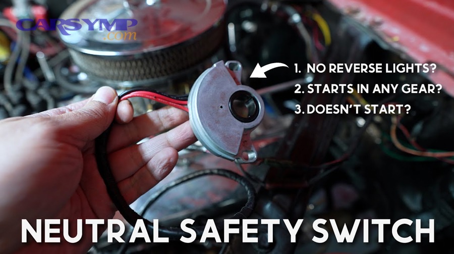
The neutral safety switch serves as a critical safety mechanism that prevents your engine from cranking while the transmission is in a drive gear. This protection stops your vehicle from lunging forward or backward unexpectedly during starting attempts, which could cause property damage or personal injury.
Located on the transmission housing or steering column depending on your vehicle’s design, the neutral safety switch monitors the position of the gear selector. The switch contains internal contacts that only close when the transmission sits in Park or Neutral. When these contacts close, they complete the electrical circuit between the ignition switch and the starter solenoid, allowing current to flow and engage the starter motor.
On automatic transmissions, the neutral safety switch typically mounts directly to the transmission case where it mechanically connects to the shift linkage. As you move the gear selector, the linkage rotates the switch mechanism, opening and closing different internal contacts. Only when properly aligned with Park or Neutral positions do the starter circuit contacts close.
The neutral safety switch also frequently controls the reverse lights circuit. When you shift into Reverse, different contacts within the same switch close to illuminate your backup lights. This dual function explains why reverse light problems sometimes accompany neutral safety switch failures.
Manual transmission vehicles use a similar safety device called a clutch safety switch or clutch interlock switch. This component mounts near the clutch pedal and requires the pedal to be fully depressed before allowing starter engagement. The operating principle remains identical—preventing engine cranking unless specific conditions are met—but the mechanical implementation differs from automatic transmission applications.
How Can You Tell If the Problem Is the Ignition Switch or Neutral Safety Switch?
The ignition switch typically causes electrical problems across multiple key positions affecting dashboard lights, accessories, and fuel pump operation, while the neutral safety switch specifically prevents cranking in Park or Neutral without affecting other electrical systems. Identifying which symptom pattern your vehicle displays immediately narrows your diagnostic focus to the correct component.
Distinguishing between these two failure modes requires careful observation of when electrical problems occur and which systems are affected. Below, we’ll examine the specific symptoms that point to each component.
What Are the Symptoms of a Faulty Ignition Switch?
A failing ignition switch creates intermittent or complete loss of electrical power to multiple vehicle systems across different key positions. The most common symptom involves the dashboard lights and accessories failing to illuminate when you turn the key to the “On” position, indicating the switch isn’t completing the circuit to the ignition/run terminal.
You might experience situations where turning the key produces no response from any electrical system—no dash lights, no fuel pump prime, and no starter engagement. This complete electrical silence differs from a dead battery because accessories work when the key is in the “Accessory” position but fail in “On” or “Start.” The switch’s internal contacts have lost continuity for specific circuits while maintaining connection for others.
Intermittent electrical issues provide strong evidence of ignition switch problems. The engine might start normally several times, then suddenly fail to crank with all electrical systems going dark. Wiggling or jiggling the key in the ignition often temporarily restores function, indicating loose or worn internal switch contacts that make inconsistent connections.
Heat-related failures commonly plague ignition switches, especially in older vehicles. The engine starts fine when cold but refuses to crank after reaching operating temperature. As the switch heats up through normal operation or from engine compartment heat, internal contacts expand and lose proper alignment. After cooling for 15-30 minutes, normal function returns until the cycle repeats.
Some ignition switches fail in ways that prevent the key from returning to the “On” position after releasing from “Start.” The key springs back but electrical power to the ignition system cuts out, causing the engine to immediately die. This symptom indicates worn detent mechanisms or damaged internal components within the switch assembly.
What Are the Symptoms of a Bad Neutral Safety Switch?
Neutral safety switch failures produce a distinctive pattern where the engine refuses to crank in Park but will crank in Neutral, or vice versa. This selective behavior occurs because the switch has partially failed, with contacts working in one position but not the other. The electrical systems function normally—dashboard lights illuminate, accessories work properly, and you hear the fuel pump prime—but turning the key to “Start” produces no response from the starter.
The opposite problem also indicates neutral safety switch issues: the engine cranks in all gear positions including Drive and Reverse. This dangerous condition means the safety function has completely failed, allowing you to start the engine while in gear. If you successfully start the engine in Drive, your vehicle lurches forward unexpectedly, creating serious safety hazards.
Many neutral safety switch problems require you to jiggle or manipulate the shifter to achieve engine cranking. Moving the gear selector slightly within the Park position, or rapidly shifting between Park and Neutral, might trigger intermittent starter engagement. This behavior signals a misaligned or worn neutral safety switch that only makes contact in very specific positions.
Reverse lights failing to illuminate when you shift into Reverse frequently accompanies neutral safety switch problems because both functions share the same component. If your backup lights stopped working around the same time starting issues began, the neutral safety switch likely contains the fault for both symptoms.
Cold weather often exacerbates neutral safety switch problems. The switch might work reliably in warm conditions but fail during winter temperatures. Thermal contraction affects the switch’s internal components and the transmission linkage that actuates it, pushing marginal switches into failure territory. This temperature sensitivity helps distinguish neutral safety switch issues from ignition switch problems, which typically worsen with heat rather than cold.

What Tools Do You Need to Test These Switches?
Testing ignition switches and neutral safety switches requires a digital multimeter for voltage and continuity checks, a 12-volt automotive test light for quick circuit verification, jumper wires for bypass testing, and basic hand tools for accessing components—typically completing diagnostic work with equipment costing under $50. These tools enable accurate electrical measurements that definitively identify faulty components without expensive diagnostic scanners.

Gathering the right equipment before beginning diagnostic work prevents interruptions and ensures you can complete all necessary tests. Let’s examine the specific tools and their applications.
What Are the Essential Testing Tools?
A digital multimeter (DMM) serves as your primary diagnostic instrument for testing both switches. Choose a multimeter with DC voltage measurement capability up to 20 volts and continuity/resistance (ohms) testing functions. The voltage testing function confirms whether electrical power reaches specific points in the circuit, while continuity testing verifies that switch contacts properly close to complete electrical pathways. Auto-ranging multimeters simplify operation by automatically selecting appropriate measurement scales, though manual models work equally well once you set them to 20V DC for voltage checks.
The 12-volt automotive test light provides faster circuit checks than a multimeter when you simply need to confirm power presence without measuring exact voltage. This tool consists of a sharp probe connected to a light bulb with a ground clip. When the probe touches a powered circuit and the clip connects to vehicle ground, the bulb illuminates. Test lights excel at back-probing connectors—inserting the probe behind connector pins while they remain plugged in—allowing you to test circuits under operating conditions without disconnecting components.
Jumper wires enable bypass testing, which proves whether a switch is faulty by temporarily removing it from the circuit. Use jumper wires with insulated handles and alligator clips on both ends, rated for at least 10 amps. Two 12-inch jumper wires handle most testing scenarios, though a set of various lengths provides flexibility. Some technicians prefer a long screwdriver with an insulated handle for making momentary jumper connections, particularly when testing the starter solenoid.
Basic hand tools complete your diagnostic kit. A socket set or combination wrenches allow you to remove components for testing or access switches hidden behind covers. Needle-nose pliers help manipulate small connectors and hold wires during testing. A wire stripper or pocket knife assists with carefully probing wires without causing damage. Keep these tools organized in a small toolbox dedicated to electrical diagnostics.
A vehicle-specific wiring diagram, while not a physical tool, proves invaluable for identifying wire colors, terminal locations, and circuit paths. Many auto parts stores provide free wiring diagrams through their online systems when you input your vehicle information. Factory service manuals contain comprehensive wiring schematics but cost significantly more than generic repair manuals. Online subscription services like AllData or Mitchell1 offer professional-grade wiring diagrams for reasonable monthly fees.
What Safety Equipment Should You Use?
Battery disconnect procedures form the foundation of safe electrical work. Before performing any tests that require removing components or probing terminals with exposed metal, disconnect the negative battery cable to prevent accidental shorts and electrical fires. Use a 10mm wrench or socket to loosen the cable clamp nut, then lift the cable end away from the battery terminal. Secure it away from the battery post with electrical tape or position it where it cannot accidentally contact the terminal during your work.
However, many diagnostic tests specifically require battery power to check circuits under operating conditions. For these live-circuit tests, exercise extreme caution to prevent short circuits. Never allow test probes, jumper wires, or metal tools to simultaneously contact positive and negative terminals or bridge powered circuits to ground. A direct short draws hundreds of amps instantly, creating sparks, melting wires, and potentially causing battery explosions or vehicle fires.
Wheel chocks and parking brake engagement prevent vehicle movement during testing. Place chocks behind the rear wheels if the vehicle sits on level ground, or both front and rear if working on any incline. Set the parking brake firmly and leave the transmission in Park (or first gear for manual transmissions). These precautions become critical when testing the neutral safety switch by bypassing it—the engine might start while in gear, causing the vehicle to lunge unexpectedly.
Protective gloves shield your hands from battery acid, sharp metal edges, and hot engine components. Nitrile or latex gloves provide adequate protection for electrical work while maintaining finger dexterity. Avoid cotton or fabric gloves that absorb battery acid or catch on moving parts. Safety glasses protect your eyes from battery acid splashes and sparks from accidental short circuits. Battery explosions, though rare, can spray sulfuric acid with enough force to cause permanent eye damage.
Keep a fire extinguisher rated for electrical fires (Class C) within easy reach when performing electrical diagnostics. Electrical fires start quickly and spread rapidly through vehicle wiring. A 5-pound ABC-rated extinguisher handles electrical fires plus any fuel-fed fires that might develop. Mount the extinguisher near your workspace rather than leaving it in your garage across the room where you might not reach it during an emergency.
How Do You Test the Neutral Safety Switch?
Testing the neutral safety switch involves checking for 12-volt power at the switch connector with the key in “Start” position, verifying continuity across switch terminals in Park and Neutral while finding no continuity in other gears, and performing a bypass test by jumping the switch terminals to confirm whether the starter engages. These three tests definitively identify whether the neutral safety switch has failed or simply needs adjustment.
Proper testing sequence prevents misdiagnosis and unnecessary part replacement. Let’s work through the complete diagnostic procedure step by step.
Where Is the Neutral Safety Switch Located?
Column shift automatic transmissions position the neutral safety switch near the base of the steering column where the shift linkage connects to the transmission selector shaft. You’ll find this switch by following the shift linkage from the steering column down toward the transmission. The switch typically mounts directly to the transmission case with two bolts, appearing as a cylindrical or rectangular component about 2-3 inches long with an electrical connector containing 3-4 wires. The linkage rod from the shifter physically rotates the switch body, aligning internal contacts with different gear positions.
Floor shift vehicles place the neutral safety switch directly on the transmission housing, usually on the driver’s side of the transmission case. For front-wheel-drive vehicles, look on the top or side of the transaxle near where the shift cables attach. Rear-wheel-drive vehicles typically mount the switch on the driver’s side of the transmission, accessible from under the vehicle. The switch threads or bolts into the transmission case, with a shaft extending into the transmission that rotates with the manual valve position inside the valve body.
Visual identification becomes easier when you know what to look for. The switch has a multi-pin electrical connector attached to it, distinguishing it from purely mechanical components. Mounted switches often show adjustment slots in their bolt holes, allowing rotational positioning for proper alignment. Some switches have a small lever arm that the shift linkage moves, while others use a direct-drive shaft that rotates the internal mechanism.
Access procedures vary by vehicle. Column shift applications usually allow you to reach the switch from under the dashboard or by opening the hood and working from above the transmission. Floor shift installations often require raising the vehicle on jack stands or a lift to access the switch from underneath. Remove any heat shields, exhaust components, or crossmembers blocking your access path. On some vehicles, you might need to remove the shift cable bracket or other minor components to clearly see and reach the switch.
Consult your vehicle’s service manual for exact location details, as manufacturers use different switch designs and mounting positions even within the same model across different years. The manual also specifies whether your vehicle’s neutral safety switch adjusts by rotation (common on column shift) or by sliding within slotted bolt holes (typical for floor shift).
How Do You Check for Power at the Neutral Safety Switch?
Checking for power at the neutral safety switch verifies that electrical current reaches the switch from the ignition switch, isolating whether problems exist upstream or within the switch itself. Begin by locating the switch connector and identifying the wire that carries power from the ignition switch. This wire typically shows as purple, purple/white, or yellow in most American vehicles, though colors vary by manufacturer. Your wiring diagram identifies the correct terminal.
Disconnect the electrical connector from the neutral safety switch by pressing the release tab and pulling the connector straight off. Inspect the connector pins for corrosion, bent contacts, or burn marks indicating previous electrical problems. Clean any corrosion with electrical contact cleaner and a small wire brush, as poor connections often cause intermittent switch operation.
With the connector disconnected from the switch, turn the ignition key to the “Start” position and hold it there. You’ll need an assistant for this test, as you must simultaneously hold the key and check for voltage. Insert the test light probe into the back of the connector housing—the side with the wires, not the pin side—targeting the power input terminal. Touch the probe to the metal terminal inside the connector while your assistant holds the key in “Start.” The test light should illuminate brightly, indicating 12 volts present.
If using a multimeter instead of a test light, set the meter to 20V DC. Connect the black (negative) lead to a good ground point on the vehicle chassis or battery negative terminal. Insert the red (positive) probe into the back of the connector to contact the power input terminal. With the key held in “Start” position, the multimeter should display approximately 12 volts (typically 11.5-13.5 volts depending on battery condition).
No voltage reading indicates a problem upstream from the neutral safety switch. The fault lies in the ignition switch, the wiring between the ignition switch and neutral safety switch, a blown fuse, or a faulty starter relay if your vehicle uses one. Check the fuse box for a blown starter or ignition fuse before condemning the ignition switch.
If voltage appears at the neutral safety switch connector, proceed to test the switch’s output. Back-probe the output terminal—the wire leading to the starter solenoid—while the connector remains plugged into the switch. Place the transmission in Park, have your assistant turn the key to “Start,” and check for voltage at the output terminal. Repeat this test with the transmission in Neutral. Voltage should appear at the output in both Park and Neutral if the switch functions properly. No voltage in either position indicates a faulty switch that requires replacement or adjustment.
How Do You Test Neutral Safety Switch Continuity?
Continuity testing reveals whether the neutral safety switch’s internal contacts properly close in Park and Neutral while remaining open in all other gear positions. This test requires removing the switch from the circuit by disconnecting its electrical connector, allowing you to check the switch independently of the vehicle’s wiring.
Set your digital multimeter to the continuity or resistance (ohms) function, usually marked with a diode symbol or “Ω” on the dial. Most multimeters emit an audible beep when continuity exists between the test leads. Touch the test leads together to verify the continuity function works—you should hear a beep or see a very low resistance reading near zero ohms.
Identify the two terminals on the neutral safety switch connector that handle starter circuit power. Your wiring diagram shows which pins carry current from the ignition switch to the starter solenoid. On most switches, these are the two largest terminals, often positioned opposite each other in the connector. Some switches include additional terminals for backup lights and other functions—ignore these for starter circuit testing.
Place one multimeter probe on each of the starter circuit terminals on the switch itself (not the connector). With the transmission in Park, check for continuity. The multimeter should beep or show near-zero resistance, indicating closed contacts. Shift the transmission to Neutral and retest—continuity should remain present. Now shift through all other gear positions (Reverse, Drive, 2, 1, etc.) and verify that continuity disappears in each position. The multimeter should not beep, or should display “OL” (overload) or infinite resistance.
A neutral safety switch showing no continuity in Park and Neutral has failed and requires replacement. However, if the switch shows continuity in Park but not Neutral (or vice versa), adjustment might restore function before resorting to replacement. Switches displaying continuity in gear positions other than Park and Neutral have failed dangerously, losing their safety function entirely.
Some neutral safety switches use normally closed contacts for the starter circuit, meaning they show continuity in all positions except Park and Neutral. This reverse-logic design is less common but appears in certain Chrysler and European vehicles. Your wiring diagram indicates whether your switch uses normally open (most common) or normally closed contacts, preventing confusion during testing.
If the switch shows proper continuity but starting problems persist, test the backup light circuit if your switch includes it. Place the transmission in Reverse and check for continuity between the backup light terminals. No continuity in Reverse suggests internal switch damage even if the starter circuit tests correctly, supporting replacement rather than adjustment.
How Do You Bypass the Neutral Safety Switch for Testing?
Bypassing the neutral safety switch proves definitively whether the switch causes your no-start condition or if problems lie elsewhere in the starting circuit. This test should only be performed after confirming that power reaches the switch from the ignition switch, as bypassing a switch that receives no power accomplishes nothing.
Critical safety warning: Bypassing the neutral safety switch allows the engine to crank while the transmission is in gear. If the engine starts, the vehicle will lunge forward or backward with enough force to cause property damage or severe injury. Before proceeding, place wheel chocks both in front of and behind at least one wheel, firmly set the parking brake, ensure no people or objects occupy the space in front of or behind the vehicle, and keep your foot firmly on the brake pedal throughout the test.
Locate the two terminals on the neutral safety switch connector that carry starter circuit power—one from the ignition switch, one to the starter solenoid. With the switch connector still disconnected, use a jumper wire to connect these two terminals together in the wiring harness side of the connector (not on the switch itself). You’re creating a direct connection that bypasses the switch entirely, allowing current to flow from ignition switch to starter solenoid regardless of transmission position.
Turn the ignition key to the “Start” position. If the starter immediately engages and cranks the engine, the neutral safety switch is faulty and requires adjustment or replacement. The bypass test proves that all other starting circuit components function correctly—the ignition switch sends power, wiring delivers current, and the starter responds—confirming the neutral safety switch as the sole problem.
If the starter clicks but won’t start, you’ve identified an additional problem. The click indicates that current flows through the bypass to the starter solenoid, activating it, but the starter motor itself fails to crank the engine. This symptom points to a faulty starter motor, poor electrical connections at the starter, or insufficient battery power to turn the starter under load. Check battery voltage under load and test the main battery cables for excessive resistance.
No response when bypassing the neutral safety switch—no click, no crank, no sound—indicates the problem lies upstream in the circuit. The ignition switch might not send power in the “Start” position, the wiring between ignition switch and neutral safety switch could be broken or corroded, or a fuse/relay in the starting circuit has failed. Return to testing for voltage at the neutral safety switch connector with the key in “Start” position to locate the fault.
After completing the bypass test, immediately remove the jumper wire and reconnect the neutral safety switch connector. Never operate your vehicle with the neutral safety switch bypassed—the safety risk is unacceptable. If the switch failed the bypass test, proceed to adjustment procedures or replacement.

How Do You Test the Ignition Switch?
Testing the ignition switch requires checking for 12-volt power at the starter solenoid “S” terminal during cranking attempts, verifying continuity through the switch in various key positions using a multimeter, and inspecting the wiring harness for damaged connections or voltage drops. These tests identify whether the ignition switch properly routes electrical power to the starting circuit and other vehicle systems.
Systematic testing prevents replacing a good ignition switch when wiring problems actually cause the symptoms. Let’s examine each testing procedure in detail.
Where Is the Ignition Switch Located?
The ignition switch mounts inside the steering column on most vehicles, separate from the key cylinder that you see and operate. The key cylinder is the mechanical lock mechanism where you insert the key, while the electrical ignition switch sits further down the column, connected to the cylinder by a rod or cable. This separation allows the electrical switch to be replaced without changing vehicle keys.
To access the ignition switch, you typically remove the plastic covers surrounding the steering column. These covers usually split into upper and lower halves, held together by Phillips screws located on the underside of the column. Remove all visible screws, then gently pry the cover halves apart. Some covers use hidden clips in addition to screws—consult your service manual to avoid breaking tabs during removal.
With the column covers removed, you’ll see the ignition switch mounted to the side or bottom of the steering column, usually held by two screws or bolts. The switch has a multi-pin electrical connector attached to it and a mechanical actuator that the key cylinder drives. On some vehicles, the switch mounts in a vertical orientation; on others, it sits horizontally.
Certain vehicles, particularly older General Motors products, use a steering column-mounted switch that sits very high in the column near the dashboard. These require removing the knee bolster panel below the steering wheel for access. European vehicles sometimes place the switch remotely from the steering column, mounting it to the dashboard or behind the instrument cluster.
Push-button start vehicles don’t have traditional ignition switches. Instead, they use a body control module or dedicated start/stop button module to control starting circuits. Testing these systems requires different procedures, often involving diagnostic scanners to read module outputs rather than direct electrical testing.
How Do You Test Voltage at the Starter Solenoid?
Testing voltage at the starter solenoid during cranking attempts reveals whether the ignition switch successfully sends power through the entire starting circuit. This test bypasses the complexity of removing and bench-testing the switch, providing a definitive answer while components remain installed in the vehicle.
Locate the starter solenoid, which typically mounts on the passenger side inner fender near the battery in Ford vehicles, or directly on the starter motor in most other makes. The solenoid has three or four terminals: a large positive battery terminal connected directly to the battery with a thick cable, a large motor terminal connected to the starter motor, and one or two small terminals for the control circuit. The “S” terminal (sometimes marked “Start” or “Sol”) receives power from the ignition switch to activate the solenoid.
Connect your voltmeter’s negative (black) lead to a good ground point on the engine block or battery negative terminal. Touch the positive (red) probe to the “S” terminal on the starter solenoid. Have an assistant turn the ignition key to the “Start” position and hold it there while you observe the voltmeter reading.
The meter should display approximately 12 volts (typically 11.5-13.5 volts) when the key reaches “Start” position. This confirms that the ignition switch closes its internal contacts, power flows through the neutral safety switch (which must be in Park or Neutral), and current successfully travels to the starter solenoid. If voltage appears but the starter doesn’t engage, the solenoid or starter motor has failed, not the ignition switch.
No voltage at the “S” terminal indicates a problem in the control circuit. The fault could be the ignition switch failing to close its starter contacts, a faulty neutral safety switch blocking current flow, broken wiring between components, or a blown fuse. Begin isolating the problem by testing for voltage at the neutral safety switch output terminal as described in the previous section.
Intermittent voltage readings—fluctuating between 12 volts and zero while holding the key in “Start”—strongly suggest a failing ignition switch with worn or corroded internal contacts. These contacts make and break connection randomly as you hold the key position, creating unreliable starter operation. Document this intermittent behavior as it confirms the need for switch replacement.
How Do You Test the Ignition Switch Directly?
Direct ignition switch testing requires removing the switch from the steering column and checking continuity between its terminals in various key positions. This bench test eliminates all other circuit variables, definitively proving whether the switch itself has failed.
Before removing the ignition switch, disconnect the vehicle’s battery negative cable to prevent accidental shorts and airbag deployment. Remove the steering column covers as described earlier, then locate the electrical connector attached to the switch. Press the connector’s locking tab and pull it straight off the switch terminals. Note the switch mounting bolt locations and remove them with the appropriate socket or wrench.
Most ignition switches have a mechanical linkage connecting them to the key cylinder. This linkage might be a flat metal rod that inserts into a slot on the switch, or a cable system. Disengage this linkage by removing a retaining clip or pushing a release tab, then slide the switch away from the column. Some switches require you to turn the key to a specific position (usually “Accessory”) before the linkage releases.
With the switch removed, identify the terminals and their functions using your wiring diagram. Common terminals include:
- Battery/BAT: Always hot, receives constant 12V from the battery
- Accessory/ACC: Powered in “Accessory” and “On” positions
- Ignition/IGN or Run: Powered in “On” and “Start” positions
- Start/ST: Only powered in “Start” position
Set your multimeter to continuity mode. The test procedure checks which terminals connect in each switch position. Create a chart documenting the expected continuity pattern:
Off Position: Battery terminal connects to nothing (all circuits open)
Accessory Position: Battery terminal connects to Accessory terminal only
On/Run Position: Battery terminal connects to both Accessory and Ignition terminals
Start Position: Battery terminal connects to Ignition and Start terminals (Accessory usually disconnected)
Manually move the switch actuator through each position while testing continuity between the battery terminal and each output terminal. The switch should match the expected continuity pattern. Any deviation indicates internal contact failure requiring switch replacement.
Pay particular attention to the “Start” position, where failures most commonly occur. The switch must show solid continuity between battery and start terminals when held in “Start.” If continuity appears intermittently or not at all, internal contacts have worn or corroded. Similarly, if the “Start” terminal shows continuity in positions other than “Start,” the switch has failed dangerously and requires immediate replacement.
Some technicians perform a voltage test instead of continuity testing by connecting a 12-volt battery to the switch’s battery terminal and using a test light to check for power at output terminals in different positions. This method simulates real-world operating conditions more accurately than continuity testing alone.
How Do You Check the Ignition Switch Wiring Harness?
Wiring harness problems between the ignition switch and other components create symptoms identical to ignition switch failure, making harness inspection essential before condemning the switch. The harness includes all wires connecting the switch to the battery, starter solenoid, fuse panel, and vehicle electrical systems.
Begin by visually inspecting the connector that plugs into the ignition switch. Remove the connector and examine both the connector body and the switch terminals for:
- Corrosion (green, white, or blue deposits on terminals)
- Burned or melted plastic indicating overheating
- Pushed-back pins that don’t make proper contact when connected
- Cracked or damaged connector body
- Oil or coolant contamination that degrades connections
Clean corroded terminals with electrical contact cleaner and a small wire brush. Severely corroded connectors require replacement—you can often purchase new pigtail connectors from auto parts stores and splice them onto existing wires using solder and heat shrink tubing.
Test each wire in the harness for continuity from the ignition switch connector to its destination. Disconnect both ends of the wire you’re testing, then check continuity between the two ends using your multimeter. The meter should beep or show near-zero resistance for good wires. No continuity indicates a broken wire hidden inside the harness insulation, requiring wire replacement or repair.
Perform voltage drop testing to identify high-resistance connections that reduce electrical flow without breaking the circuit entirely. These subtle faults cause intermittent operation that continuity testing misses. Connect your voltmeter to measure voltage drop across each connection point while the circuit carries current.
For example, to test the main power feed to the ignition switch, connect the voltmeter’s positive lead to the battery positive terminal and the negative lead to the battery input terminal on the ignition switch connector. Turn on electrical loads (headlights, blower motor) to draw current through the circuit. The voltmeter should read less than 0.1 volts. Higher readings indicate excessive resistance in the wiring or connections, causing voltage loss before power reaches the switch.
Check the ground circuit similarly. Connect the voltmeter between the ignition switch ground terminal and the battery negative terminal while electrical loads operate. Again, voltage drop should remain below 0.1 volts. Excessive voltage drop in ground circuits causes the same symptoms as poor positive connections—intermittent operation and voltage-sensitive failures.
The “Start” circuit wire deserves special attention as it carries high current loads when engaging the starter solenoid. This wire runs from the ignition switch through the neutral safety switch to the starter solenoid “S” terminal. Inspect this wire’s entire length for chafing, melting, or damage where it passes through firewalls or near hot exhaust components. Even minor damage creates resistance that prevents adequate current flow to activate the solenoid reliably.
Wiring diagrams reveal whether your vehicle uses fuses or relays in the starting circuit. Locate and test these components by substituting known-good parts or performing continuity checks with power removed. A blown fuse in the starter circuit prevents operation regardless of ignition switch condition. Failed relays produce clicks without starter engagement—the relay coil energizes but contacts don’t close to pass high current to the starter.
How Do You Interpret Test Results to Identify the Faulty Component?
Test results pointing to 12 volts at the starter solenoid “S” terminal indicate a working ignition switch and neutral safety switch with the fault in the starter solenoid or motor, while no voltage at this terminal requires back-tracking through the circuit to find where voltage is lost—at the neutral safety switch, ignition switch, or wiring connections. Systematic interpretation of your electrical measurements eliminates guesswork and confirms exactly which component needs attention.
Understanding what each test result means guides you toward the correct repair. Let’s decode the most common test scenarios.
What Do Your Test Results Mean?
Scenario 1: Voltage present at starter solenoid “S” terminal, but no cranking
This result proves that both your ignition switch and neutral safety switch function correctly—they’re completing the circuit and delivering power where needed. The problem lies in the starter system itself. The starter solenoid may have failed internally, unable to engage despite receiving the trigger signal. Alternatively, the starter motor could be seized, heavily corroded, or electrically defective. The tap test myth suggests that tapping the starter motor with a hammer might temporarily restore function by unseating stuck brushes or freeing a jammed armature, and what it indicates is typically a failing starter motor with worn internal components rather than an electrical circuit problem.
Scenario 2: No voltage at starter solenoid “S” terminal, but voltage present at neutral safety switch output
The neutral safety switch is sending power forward, but it’s not arriving at the solenoid. Inspect the wire connecting these two components for breaks, corrosion, or loose connections. Check for blown fuses in this section of the circuit. Some vehicles use a starter relay between the neutral safety switch and solenoid—test this relay by substitution or by checking for voltage at both its input and output terminals.
Scenario 3: No voltage at neutral safety switch output, but voltage present at its input
The neutral safety switch has failed. It receives power from the ignition switch successfully, but internal contacts won’t close to pass current through to the starter circuit. Attempt adjustment procedures before replacing the switch, as misalignment often causes this symptom. If adjustment doesn’t restore function, replace the switch.
Scenario 4: No voltage at neutral safety switch input
The ignition switch isn’t sending power to the starting circuit. Test voltage directly at the ignition switch output terminal. If voltage appears there but not at the neutral safety switch, the connecting wire has broken or corroded. If no voltage appears at the ignition switch output even in “Start” position, the ignition switch has failed internally and requires replacement.
Scenario 5: Voltage present at all test points, starter engages and cranks, but engine won’t start
Your ignition switch and neutral safety switch both work perfectly. The no-start condition relates to fuel delivery, spark, compression, or timing issues unrelated to the starting circuit. Shift your diagnostic focus to the engine management system, fuel system, and ignition system. After repair, confirming charging and battery health ensures the vehicle’s entire electrical system remains in good condition.
Scenario 6: Intermittent voltage at any test point
Intermittent electrical connections plague starting circuits, creating frustrating “works sometimes, fails other times” conditions. Wiggle wiring harnesses and connectors while monitoring voltage to identify loose connections. Intermittent failures at the ignition switch itself indicate worn internal contacts requiring switch replacement. Temperature-related intermittent failures—working when cold, failing when hot—commonly affect ignition switches as internal components expand with heat.
Scenario 7: Bypass test makes starter engage, but normal operation doesn’t
When bypassing the neutral safety switch allows starter engagement but normal operation through the switch doesn’t work, the switch has definitively failed. The bypass test eliminates all variables, proving that power can successfully trigger the starter if it reaches the solenoid. Since power doesn’t arrive during normal operation through the switch, the switch must be blocking current flow.
Document your test results with notes including voltage measurements, which test points showed problems, and any intermittent behaviors observed. This documentation helps if you need to return defective parts under warranty or if symptoms return after repairs, providing a baseline for comparison.
Is It Possible Both Switches Are Faulty?
Yes, both the ignition switch and neutral safety switch can fail simultaneously, though this scenario occurs rarely because the components wear at different rates and experience different operating stresses. When both switches fail, you’ll observe a combination of symptoms that don’t fit the typical pattern for either component alone.
Sequential failure patterns provide the most likely route to dual-switch problems. A failing ignition switch might cause intermittent starting issues, leading you to repeatedly cycle the key while manipulating the shifter, hoping to trigger starter engagement. This excessive shifting and key cycling can accelerate wear on the neutral safety switch, particularly if it was already borderline due to age or contamination. The neutral safety switch then fails soon after the ignition switch begins having problems.
High-mileage vehicles (200,000+ miles) experience age-related deterioration across all electrical components simultaneously. If your vehicle has never had ignition or neutral safety switch replacement, both components might reach end-of-life around the same time. Corrosion from water intrusion affects multiple components in the same area—if the steering column leaked water onto the ignition switch, that same moisture likely contaminated the neutral safety switch through humidity accumulation in the transmission area.
Testing both switches independently using the procedures outlined earlier prevents misdiagnosis when both have failed. Start by verifying whether power leaves the ignition switch in “Start” position. If it doesn’t, the ignition switch has failed. Next, even though the ignition switch is bad, temporarily jumper it to send power to the neutral safety switch input, then test whether the neutral safety switch passes that power through to the starter solenoid. This sequential testing identifies whether one or both switches need replacement.
Electrical system abuse accelerates dual failures. Jump-starting the vehicle incorrectly (reversed polarity) sends voltage spikes through the entire electrical system, potentially damaging multiple switches, relays, and control modules simultaneously. Similarly, aftermarket alarm systems or remote starters incorrectly wired into the starting circuit can overload components, causing premature failures across multiple parts.
When replacing one switch resolves some symptoms but starting problems partially persist, suspect the second switch. For example, if replacing the neutral safety switch eliminates the “won’t start in Park” symptom but the starter still won’t engage, and you notice that dashboard lights dim when turning the key, focus testing efforts on the ignition switch. The partial improvement confirms the neutral safety switch replacement was necessary, while remaining symptoms point toward a second, independent fault.
Budget for both switches when you find one definitively failed on a high-mileage vehicle. While replacing only the confirmed-bad component makes immediate sense, labor costs for accessing and replacing either switch often exceed parts costs. Replacing both simultaneously prevents a second expensive repair visit weeks or months later when the marginally-functional second switch finally fails completely.

Can You Adjust the Neutral Safety Switch Instead of Replacing It?
Yes, many neutral safety switch failures result from misalignment rather than internal damage, allowing adjustment to restore proper function without replacement—rotating or sliding the switch body until internal contacts align correctly with Park and Neutral positions saves $50-$150 in parts costs. Adjustment succeeds when the switch shows correct continuity in testing but only in positions slightly offset from where Park and Neutral actually sit, indicating the mechanical alignment has shifted rather than electrical components failing.

Understanding when adjustment works versus when replacement is necessary prevents wasted time and ensures reliable repairs. Let’s explore the adjustment process and its limitations.
How Do You Adjust a Neutral Safety Switch?
Adjusting a neutral safety switch realigns its internal contacts with the transmission’s Park and Neutral positions, restoring the switch’s ability to complete the starter circuit in the correct gear positions. This procedure works only when internal switch components remain functional but mechanical alignment has drifted from specifications.
Begin by locating the switch mounting bolts and verifying they allow adjustment. Most neutral safety switches mount with slotted bolt holes that permit rotating or sliding the switch body while bolts remain loosened but not removed. Column shift switches typically adjust by rotation around their axis, while floor shift transmission-mounted switches usually slide linearly within their mounting slots.
Place the transmission firmly in Park and set the parking brake. Ensure the vehicle sits on level ground with wheel chocks in place, as you’ll be attempting to start the engine during the adjustment process. Disconnect the negative battery cable if you feel uncomfortable with live electrical work, though you’ll need to reconnect it for each adjustment attempt.
Loosen the neutral safety switch mounting bolts enough to allow the switch to move but not so much that it falls off or rotates freely. Typically, loosening the bolts 2-3 turns provides adequate freedom of movement while maintaining enough friction to hold the switch position once you release it. Some switches use special adjustment tools—flat plates with pins that engage holes in the switch body—but most adjust fine with just a wrench or socket holding the bolts slightly loose.
Have an assistant sit in the driver’s seat, foot firmly on the brake pedal, ready to turn the ignition key to “Start” position. Position yourself where you can reach the neutral safety switch to manipulate it while remaining clear of moving parts and hot exhaust components. Your assistant should turn the key to “Start” and hold it there while you slowly rotate or slide the switch.
As you adjust the switch position, listen for the starter to engage. The moment you hear the starter begin to crank, stop moving the switch and hold it in that exact position. Call to your assistant to release the ignition key immediately—you don’t want the engine to actually start during this process. While holding the switch firmly in the position where cranking occurred, tighten the mounting bolts to specification (typically 8-12 ft-lbs, but consult your service manual).
After tightening the bolts, verify the adjustment across all relevant positions. Attempt to start the engine in Park—it should crank normally. Shift to Neutral and verify cranking occurs there as well. Critically important: shift to Reverse, Drive, and any other forward gears, attempting to start the engine in each position. The starter should NOT engage in any gear position other than Park and Neutral. If it cranks in Drive or Reverse, you’ve adjusted the switch incorrectly, creating a dangerous situation where the vehicle can start while in gear.
Some vehicles provide alignment marks on the neutral safety switch and transmission case that should align when the switch is properly positioned. These marks appear as small notches, raised dots, or stamped indicators. If your switch has alignment marks, position them correctly as a starting point before fine-tuning the adjustment with the cranking test described above.
The alignment pin method provides the most precise adjustment on switches designed for it. These switches have a small hole in the body that aligns with a corresponding hole in the transmission selector shaft when both are in Neutral position. Insert a drill bit or alignment pin (usually 3/32″ or 1/8″ diameter) through both holes, locking the switch and shaft in perfect alignment. Tighten the mounting bolts with the pin inserted, then remove the pin and test operation.
After completing the adjustment and verifying proper operation in all gear positions, test the reverse lights. Shift into Reverse with the ignition on—your backup lights should illuminate. No reverse lights despite proper starter operation indicates internal switch damage affecting the backup light circuit even though the starter circuit works. This confirms the switch has partially failed and requires replacement regardless of successful adjustment.
When Should You Replace Instead of Adjust?
Replace the neutral safety switch when adjustment attempts fail to restore proper starter operation, when the switch shows no continuity in any position during bench testing, when visible damage or contamination affects the switch body or connector, or when intermittent failures persist after successful adjustment. Certain failure modes indicate internal damage that adjustment cannot fix.
Internal electrical contact failure represents the most common reason adjustment doesn’t work. If testing reveals that the switch shows no continuity in Park and Neutral regardless of how you position the switch body, internal contacts have corroded, worn, or broken apart. Adjustment only works when contacts function properly but sit misaligned with transmission positions. Non-functional contacts require switch replacement.
Physical damage to the switch housing, mounting tabs, or adjustment slots eliminates the possibility of proper alignment even if internal components work. Cracks in the plastic housing allow moisture intrusion that corrodes internal contacts. Stripped adjustment slots prevent secure mounting at any position. Broken actuator arms that connect to the shift linkage can’t transmit shifter position to internal contacts. Any of these mechanical failures mandate replacement.
Extreme internal contamination ruins neutral safety switches beyond adjustment. Transmission fluid leaking past seals into the switch body creates sticky residue on contacts that prevents reliable electrical connection. Road salt and water intrusion on transmission-mounted switches cause corrosion that no amount of adjustment overcomes. If you find thick deposits, rust, or fluid contamination when removing the switch, replacement provides the only reliable repair.
Intermittent operation after successful adjustment suggests internal components have degraded despite making contact in test conditions. The switch might work perfectly during static bench testing and immediately after adjustment, then fail randomly during vehicle operation due to vibration, temperature changes, or subtle movements in the linkage. These marginal switches typically fail completely within weeks or months, requiring eventual replacement anyway.
Age and mileage guidelines help determine whether adjustment makes sense as a repair strategy. On vehicles over 15 years old or with 150,000+ miles, neutral safety switches approaching end of service life often adjust successfully but fail again within months as worn components continue degrading. In these cases, replacing the switch during initial service prevents comeback repairs and provides better long-term reliability despite higher initial cost.
Cost-benefit analysis favors replacement on late-model vehicles with expensive switches that include additional features. Modern neutral safety switches often integrate shift position sensors, backup light switches, and range selection signals for the transmission control module into a single $150-$300 assembly. While mechanical adjustment might restore starting function, degraded position sensors trigger transmission warning lights and erratic shift behavior that persist after adjustment. Full switch replacement resolves all symptoms simultaneously.
Labor accessibility strongly influences the replacement versus adjustment decision. If your vehicle requires extensive disassembly to access the neutral safety switch—dropping exhaust systems, removing crossmembers, or draining transmission fluid—the labor cost of accessing the switch often exceeds the parts cost. When you’ve already invested hours accessing the component, replace it rather than risk needing to repeat that access work after an adjustment fails to hold.
Warranty coverage tilts the decision toward replacement. Reputable parts suppliers warranty new neutral safety switches for 1-3 years, protecting against defective parts and providing free replacement if failure reoccurs. Adjustment carries no warranty—if the switch fails again next week, you’ve gained nothing from the time and effort invested in adjustment. From a reliability and economics standpoint, replacement often proves more cost-effective than adjustment on critical safety components.
What Other Starting Circuit Components Could Cause Similar Symptoms?
The starter solenoid, battery cables, battery condition, starter motor, and wiring harness connections can all produce no-crank symptoms identical to ignition switch or neutral safety switch failures, requiring systematic testing of each component to isolate the actual fault. A clicking starter solenoid indicates power reaches it but something prevents the starter motor from engaging, while complete silence suggests no power flows through the circuit at all.

Expanding diagnostic scope beyond just the two primary switches prevents unnecessary parts replacement and identifies the true fault. Let’s examine the other common culprits in starting circuit failures.
How Do You Test the Starter Solenoid?
The starter solenoid acts as a high-current relay that connects battery power to the starter motor only when you turn the key to “Start.” The solenoid receives a low-current trigger signal from the ignition switch and neutral safety switch at its “S” terminal, which energizes an electromagnet that pulls a heavy-duty contact closed, completing the circuit between the battery and starter motor.
A failing solenoid produces a distinctive clicking sound when you turn the key—you hear the electromagnet activate and the internal contacts attempt to close, but they either fail to make solid connection or immediately open again under load. This click-no-crank symptom differs from complete silence (which indicates no trigger signal reaches the solenoid) and from grinding or whining noises (which indicate starter motor problems).
To test whether the solenoid can handle high current loads, perform a bypass test using a screwdriver or jumper cable. Safety warning: This test creates sparks and potentially dangerous current flow. Wear safety glasses, remove jewelry, and ensure no flammable materials sit near the battery or starter. Verify the transmission is in Park or Neutral, set the parking brake, and place wheel chocks around the tires.
Locate the two large terminals on the starter solenoid—one connects directly to the battery positive terminal via a thick cable, the other connects to the starter motor. Using an insulated screwdriver or heavy jumper cable, carefully connect these two large terminals together. This bypasses the solenoid’s internal contacts, sending battery power directly to the starter motor.
If the starter immediately engages and cranks the engine vigorously, the solenoid contacts have failed even though the electromagnet works (hence the click). Replace the solenoid, which on most vehicles means replacing the entire starter assembly as the solenoid isn’t sold separately. If the starter still won’t crank despite the bypass, the starter motor itself has failed or battery power is insufficient.
Performing a voltage drop test reveals poor connections or internal resistance within the solenoid without bypassing it. Connect your voltmeter to measure voltage across the solenoid—positive lead on the battery side large terminal, negative lead on the starter motor side large terminal. Have an assistant turn the key to “Start” while you observe the meter. During cranking, voltage drop across a good solenoid should remain below 0.5 volts. Higher readings indicate excessive resistance in the solenoid contacts, confirming internal wear or corrosion.
Some starter solenoids fail intermittently due to heat sensitivity. The solenoid works fine when cold but refuses to engage after the engine reaches operating temperature. Heat causes internal components to expand, preventing proper contact closure. If you experience heat-related starting failures, allow the engine to cool completely, then test the solenoid. If it works cold but fails hot, heat-related solenoid failure is confirmed.
How Do Battery and Cable Issues Mimic Switch Problems?
Battery and cable problems create no-crank conditions that perfectly mimic neutral safety switch or ignition switch failures, but they stem from insufficient electrical power rather than incomplete circuits. A weak battery or corroded cables can’t deliver the 200-400 amps required to crank the engine, even though they supply enough current to power low-draw systems like lights and radio.
The classic symptom involves dashboard lights illuminating normally when you turn the key to “On,” but dimming significantly or going completely dark when you turn to “Start.” This behavior indicates the battery has enough capacity for low-current draws but collapses under the heavy load of starter engagement. Your neutral safety switch and ignition switch are working perfectly—they’re completing circuits as designed—but inadequate power prevents the starter from turning.
Battery voltage testing requires checking both resting voltage and voltage under load. Use your multimeter to measure battery voltage with the engine off and all accessories off. A fully charged battery reads 12.6-12.8 volts. Readings below 12.4 volts indicate a partially discharged battery that may not crank the engine reliably. Below 12.0 volts, the battery is significantly discharged and almost certainly won’t start the vehicle.
Load testing provides more definitive results than voltage measurement alone. Have an assistant turn the key to “Start” and hold it while you monitor battery voltage. During cranking attempts, voltage should not drop below 9.5-10.0 volts on a healthy battery. If voltage plummets to 7-8 volts or lower, the battery cannot supply adequate current under load regardless of its resting voltage. Replace the battery before troubleshooting other starting circuit components.
Battery cable condition critically affects starting performance because they carry the highest current in the entire vehicle. Corrosion at the battery terminal connections creates resistance that prevents full current flow. The white, blue, or green crusty deposits that form where cables attach to battery posts increase resistance exponentially—even minor visible corrosion can prevent starting.
Remove both battery cables and inspect the cable ends and battery posts carefully. Clean all corrosion using a battery terminal brush or wire brush and baking soda solution. The terminal clamps and battery posts should appear bright and shiny after cleaning. Merely cleaning the outside of the connection isn’t sufficient—corrosion often hides between the cable clamp and post where you can’t see it. Disassemble, clean thoroughly, and reassemble.
The negative (ground) cable deserves special attention because it completes the electrical circuit for all vehicle systems. Follow the negative cable from the battery to where it bolts to the engine block or chassis. Remove this bolt and inspect the connection point. The metal-to-metal contact area should be clean, bare metal without paint, rust, or corrosion. Clean the bolt, cable end, and chassis/engine mounting point with a wire brush until bare metal shines. Poor ground connections create the same symptoms as bad switches—intermittent operation, heat sensitivity, and seemingly random failures.
Perform voltage drop testing on both positive and negative battery cables to identify hidden internal resistance. Connect your voltmeter positive lead to the battery positive post, negative lead to the starter motor positive terminal. During a cranking attempt (or simulated high-current draw), voltage drop should remain below 0.5 volts. Repeat the test on the negative cable by connecting between battery negative post and engine block. Excessive voltage drop in either cable indicates internal corrosion or damage requiring cable replacement.
Cable replacement becomes necessary when cleaning doesn’t restore performance or when cables show obvious damage. Look for frayed strands, cracked or melted insulation, or cables that feel stiff rather than flexible. Factory cables typically last 10-15 years before internal corrosion degrades conductivity enough to affect starting. Aftermarket replacement cables often use lower-quality copper that corrodes faster—if your vehicle has already had cable replacement, they might need replacing again sooner than expected.
Could the Problem Be the Starter Motor Itself?
Starter motor failure produces several distinct symptom patterns that mimic neutral safety switch problems but stem from mechanical or electrical issues within the starter assembly. Understanding these patterns helps you differentiate starter problems from switch failures without removing components for bench testing.
The “single click” symptom indicates the starter solenoid engages successfully (creating the click) but the starter motor won’t turn. This occurs when the solenoid plunger successfully moves to engage the starter pinion with the flywheel ring gear, but the motor itself is seized, has a dead spot in the armature, or suffers from worn brushes that won’t conduct current. The click confirms that your ignition switch and neutral safety switch work correctly—they’re sending power to activate the solenoid—but the starter motor can’t convert electrical power into mechanical rotation.
Grinding or screeching noises during cranking attempts indicate the starter pinion gear is engaging the flywheel but slipping or failing to mesh properly. This mechanical failure creates noise without effective cranking. The electrical circuit (including both switches) functions correctly, but mechanical components inside the starter have worn. A worn starter drive (Bendix drive) fails to fully engage the pinion with the flywheel ring gear, causing grinding. Worn or broken teeth on either the starter pinion or flywheel ring gear create similar symptoms.
Slow cranking followed by complete failure suggests progressive starter motor degradation. The engine cranks slower than normal for several starts, then refuses to crank at all. Worn starter motor brushes create this symptom pattern—as carbon brushes wear shorter, they make poorer contact with the armature commutator, increasing resistance and reducing motor power. Eventually brushes wear so short they lose contact completely, preventing any starter operation.
The starter works intermittently, cranking the engine perfectly sometimes but producing only clicks or no response at other times. This frustrating symptom makes many technicians suspect switch problems, but it commonly indicates a dead spot in the starter motor armature. The armature is the rotating electrical component inside the starter motor that creates torque. If the armature stops in a position where its commutator segments don’t align with brushes correctly, current can’t flow and the motor won’t turn. When the armature rests in a good position, the starter works normally.
The tap test myth suggests that striking the starter motor housing with a hammer while someone turns the key can temporarily restore function to a failing starter. What it indicates is actually a stuck or frozen starter motor that has seized due to worn bearings, debris between moving parts, or a jammed starter drive mechanism. Tapping sometimes frees these stuck components temporarily, allowing the starter to engage for one or two starts before it jams again. While this trick might get you home or to a repair shop, it confirms the starter requires replacement rather than indicating an intermittent electrical problem.
Heat-related starter failures occur when the starter works fine on a cold engine but refuses to crank after the engine reaches operating temperature or immediately after shutdown when heat-soaks from the engine into the starter. Starter motors mounted close to exhaust manifolds or turbos experience extreme temperatures that can cause premature failure. Heat causes internal clearances to change as components expand, potentially jamming the armature or increasing friction in worn bearings enough to prevent rotation.
Bench testing the starter provides definitive diagnosis but requires removing it from the vehicle. Most auto parts stores offer free starter testing services—they connect the starter to a test bench that applies battery power while measuring current draw and rotation speed. A good starter draws 100-200 amps while spinning freely at 2,000-3,000 RPM. Excessive current draw (300+ amps) indicates internal shorts or mechanical binding. Insufficient current draw with no rotation indicates open circuits, failed brushes, or armature problems.
If you lack access to professional testing equipment, perform a simple bench test using jumper cables and your battery. Securely clamp the starter in a vise, ensuring it cannot jump free when it engages (starters produce substantial torque). Connect a heavy jumper cable from the battery positive terminal to the starter motor main terminal (not the solenoid “S” terminal). Touch a second jumper cable from battery negative to the starter housing for just 1-2 seconds. The starter should spin vigorously, ejecting the pinion gear as it rotates. If the starter sits motionless or spins weakly, internal failure is confirmed.
What About Problems in the Wiring Between Components?
Wiring harness issues between starting circuit components create intermittent, confusing symptoms that often lead to misdiagnosis and unnecessary part replacements. These problems range from broken wires that completely interrupt circuits to subtle high-resistance connections that allow some current flow but not enough to operate components reliably.
Broken wires typically result from physical damage—abrasion against sharp metal edges, melting from contact with hot exhaust components, or fracturing from repeated flexing in vibration-prone areas. The insulation might appear intact while copper conductors inside have completely severed. These breaks create open circuits that testing easily identifies, but locating the actual break point requires patience and methodical testing along the wire’s length.
To find a break in suspected wires, disconnect both ends and check continuity between them using your multimeter. No continuity confirms a break exists somewhere in that wire. Begin tracing the wire from one end, checking continuity every 6-12 inches until you find the point where continuity disappears. The break sits between your last good reading and the current bad reading. Access that section of harness, cut out the damaged portion, and splice in new wire using solder and heat-shrink tubing.
Chafed insulation creates intermittent shorts to ground that randomly interrupt circuit operation. The wire rubs against metal bodywork or sharp edges, wearing through insulation until bare copper contacts the grounded chassis. Sometimes the bare wire touches ground continuously, creating a dead short. More commonly, vibration and movement cause intermittent contact—the wire touches ground briefly during bumps or rough roads, causing temporary circuit interruption.
Inspect the entire length of wiring harnesses for insulation damage, paying special attention to areas where wires pass through firewalls, near moving steering components, and anywhere harnesses rest against metal brackets or sharp edges. Look for shiny copper strands visible through worn insulation, melted or discolored insulation indicating heat damage, or stiff, cracked insulation that has lost flexibility from age.
Connector corrosion produces high-resistance connections that allow partial current flow insufficient for proper operation. Each connector in the starting circuit introduces potential resistance—resistance increases as corrosion builds on terminals and moisture degrades metal-to-metal contact. The circuit might pass continuity testing (indicating a complete path) while still having too much resistance to carry adequate current under load.
Disconnect every connector in the starting circuit and inspect terminals for:
- Green, white, or blue corrosion deposits
- Dull or tarnished metal surfaces instead of shiny copper or tin
- Bent pins that don’t make firm contact when connected
- Oil or fluid contamination creating insulating films
- Moisture inside connector bodies
Clean corroded terminals with electrical contact cleaner and a small wire brush or fine sandpaper. Replace connectors showing severe corrosion or damaged terminals—connector repair kits from auto parts stores include new terminal pins and connector bodies for common applications. After cleaning, apply dielectric grease to terminals before reconnecting to prevent future corrosion.
Temperature-sensitive wiring problems create the most challenging diagnostic scenarios. The circuit works perfectly at normal temperatures but fails when heat or cold causes expansion or contraction that breaks marginal connections. A connector might make adequate contact at room temperature but separate slightly when under-hood temperatures reach 200°F during extended driving. Conversely, extreme cold might cause plastic connector bodies to contract, pulling terminals apart just enough to interrupt circuits.
Diagnosing temperature-sensitive faults requires inducing the failure while monitoring circuits. Use a heat gun to warm suspect connectors and wiring while checking for circuit interruption, or spray them with freeze spray (available at electronics supply stores) to simulate extreme cold. When the circuit fails, immediately check whether the affected connection has opened or increased in resistance.
Voltage drop testing identifies high-resistance connections that continuity testing misses. Measure voltage drop across each connector while the circuit carries current. For example, test the connector at the neutral safety switch by placing your voltmeter leads on the connector terminals on opposite sides—one probe touching the harness terminal, the other touching the switch terminal, with the connector fully assembled and the circuit energized. Voltage drop across a good connector should measure less than 0.1 volts. Higher readings indicate resistance in that connection requiring cleaning or replacement.
Wire gauge matters significantly in high-current circuits like the starting system. Factory wiring uses appropriately sized conductors—typically 10-12 gauge for low-current trigger signals and 4-6 gauge for high-current battery cables. If previous owners or technicians repaired wiring using undersized wire, resistance increases and voltage drop becomes excessive. When replacing damaged wiring, always use wire matching or exceeding the original gauge size. A 14-gauge wire might test as continuous and even carry 5-10 amps without obvious problems, but it can’t handle the current surges involved in starter engagement, creating intermittent failures under load.
This comprehensive guide has provided you with systematic testing procedures to identify whether the ignition switch, neutral safety switch, or another starting circuit component is preventing your vehicle from cranking. By following the voltage testing, continuity checks, and bypass procedures outlined, you can confidently diagnose the problem, make informed repair decisions, and restore reliable starting operation. Remember that proper testing eliminates guesswork, prevents unnecessary part replacement, and ensures your repairs address the actual fault rather than just symptoms.