


Testing a starter motor circuit with a multimeter involves checking voltage at the battery and starter terminals, testing solenoid continuity and trigger voltage, measuring motor winding resistance, and verifying ground circuit integrity to identify failures in the starting system. This systematic approach requires a digital multimeter, basic safety equipment, and following proper testing sequences to pinpoint whether issues stem from the battery, cables, solenoid, or motor itself.
Understanding the equipment requirements ensures accurate testing results. You need a digital multimeter capable of measuring DC voltage up to 20 volts, resistance in the milliohm range, and continuity testing functions. Safety equipment including insulated gloves and eye protection prevents electrical hazards during testing procedures. Proper workspace preparation, including battery disconnect protocols and securing loose clothing, creates a safe environment for diagnostic work.
Mastering the testing procedures builds diagnostic confidence. Voltage testing reveals power delivery issues through the circuit, solenoid testing identifies control and switching failures, and resistance measurements expose motor winding problems. Each test follows a specific probe placement and measurement interpretation protocol that distinguishes between normal operation and component failure. These procedures work together to create a complete diagnostic picture of starter system health.
Interpreting multimeter readings accurately separates functional components from failed parts. Next, we’ll explore each testing procedure in detail, starting with the essential equipment and safety preparations that ensure successful diagnostics.
What Equipment Do You Need to Test a Starter Circuit with a Multimeter?
Testing a starter circuit requires a digital multimeter with DC voltage and resistance functions, safety equipment including insulated gloves and eye protection, and basic hand tools for accessing connections. Specifically, your multimeter must measure 0-20V DC for voltage tests, read resistance down to 0.1 ohms for cable testing, and include a continuity function with audible beep for quick connection verification.

What Type of Multimeter Should You Use for Starter Testing?
A digital multimeter outperforms analog models for starter testing because it provides precise numerical readings, faster response times, and better accuracy in the low-voltage ranges common in automotive systems. Digital meters display voltage readings to 0.01V precision, which matters when identifying voltage drops of 0.2V or less in cable connections. Auto-ranging digital multimeters eliminate the need to manually select voltage scales, reducing testing errors and speeding up the diagnostic process.
Your multimeter must include these essential functions:
- DC voltage measurement: 0-20V range minimum, with 0.01V resolution for detecting small voltage drops
- Resistance measurement: 0-200 ohms range with milliohm precision for testing motor windings and cable resistance
- Continuity testing: Audible beep function for quick verification of complete circuits without watching the display
- Quality test leads: Leads with sharp probe tips that penetrate corrosion and secure alligator clips for hands-free testing
Professional-grade automotive multimeters cost between $50-150 and include additional features like min/max recording, data hold functions, and backlit displays for working in dim engine compartments. However, a basic digital multimeter meeting the specifications above performs all necessary starter circuit tests effectively.
What Safety Equipment Is Required Before Testing?
Safety equipment protects against electrical hazards, battery acid exposure, and mechanical injuries during starter testing procedures. Personal protective equipment creates barriers between you and the electrical system’s potential dangers, including arc flash, chemical burns, and pinch points from engine components.
Essential safety equipment includes:
- Safety glasses with side shields: Protect eyes from battery acid splashes and sparks during connection or disconnection of battery terminals
- Insulated work gloves: Rated for electrical work, these prevent shock from accidental contact with live circuits and protect hands from sharp edges
- Long-sleeved cotton clothing: Natural fibers resist ignition better than synthetics if sparks occur during testing
- Battery terminal protectors: Apply after disconnecting cables to prevent accidental contact during testing
Before beginning any starter circuit testing, disconnect the negative battery cable to eliminate the risk of short circuits when probing connections. This single step prevents accidental starter engagement, protects against arc flash when tools contact battery terminals, and creates a controlled testing environment. Reconnect the battery only when specific tests require power flow through the circuit, then immediately disconnect again after completing those measurements.
Remove jewelry, watches, and loose clothing that could contact battery terminals or become caught in moving engine components. Position yourself with stable footing and adequate lighting to clearly see connection points. Keep a fire extinguisher rated for electrical fires within reach when working with automotive electrical systems.
How Do You Test Starter Motor Voltage with a Multimeter?
Test starter motor voltage by measuring battery voltage at rest (should read 12.4-12.7V), then measuring voltage at the starter terminal during cranking (should remain above 10.5V) to verify adequate power delivery through the circuit. To begin, set your multimeter to DC voltage mode in the 20V range, connect the black lead to the battery negative terminal, and touch the red lead to various points in the circuit while observing voltage readings.
Voltage testing reveals two critical starter circuit conditions: whether sufficient voltage exists at the source and whether voltage drops excessively as current flows through cables and connections. A fully charged battery provides 12.6V at rest, but voltage naturally drops to 10.5-11.5V during cranking due to the high current draw of the starter motor. Excessive voltage drop below 10.5V indicates resistance in cables, corroded connections, or an undersized battery for the application.

How Do You Check Battery Voltage to the Starter?
Battery voltage testing follows a two-step process: measuring resting voltage with the engine off, then measuring cranking voltage while attempting to start the engine. Connect your multimeter’s black lead to the battery negative terminal and the red lead to the battery positive terminal. A healthy, fully charged battery displays 12.4-12.7V at rest. Readings below 12.4V indicate a discharged battery that requires charging before further testing, as low battery voltage creates false failure symptoms in otherwise functional starter circuits.
Next, have an assistant turn the ignition key to the start position while you monitor the multimeter display. Cranking voltage should remain above 10.5V throughout the starting attempt. If voltage drops below 10.5V, either the battery lacks sufficient capacity or excessive resistance exists in the circuit. To distinguish between these conditions, perform a second voltage measurement at the starter motor’s main terminal while cranking.
Connect the multimeter’s red lead directly to the large terminal on the starter where the positive battery cable attaches. Keep the black lead on the battery negative terminal. During cranking, this measurement should read within 0.5V of the voltage measured at the battery. For example, if battery voltage drops to 11.0V during cranking, the starter terminal should show at least 10.5V. Greater voltage differences indicate high resistance in the positive cable or its connections.
How Do You Perform a Voltage Drop Test on Starter Cables?
Voltage drop testing measures resistance in cables and connections by detecting the voltage lost between two points in an energized circuit. This test requires the circuit to carry current, so you must reconnect the battery and perform measurements during actual cranking attempts. Proper voltage drop testing reveals cable and connection problems that don’t appear during static resistance measurements.
To test the positive cable voltage drop, connect your multimeter’s black lead to the battery positive terminal and the red lead to the starter motor’s main terminal. With these connections in place, have an assistant crank the engine while you observe the multimeter. The reading shows voltage lost in the positive cable path. Acceptable voltage drop measures 0.2V or less. Readings above 0.3V indicate excessive resistance from corroded connections, damaged cable strands, or undersized cables.
Test the ground cable using the same principle with reversed connections. Place the multimeter’s red lead on the battery negative terminal and the black lead on the starter motor housing or a clean engine ground point. During cranking, this measurement reveals ground path resistance. The ground circuit should show no more than 0.1V drop. Higher readings point to corroded ground connections, damaged ground straps, or inadequate grounding between the engine and chassis.
Common voltage drop failure points include:
- Battery terminal connections: Corrosion under terminal clamps creates resistance even when connections appear tight
- Cable junction points: Crimp connections and solder joints deteriorate over time, especially in high-heat engine compartments
- Solenoid connections: The battery cable bolts to the solenoid before continuing to the motor, and these connections corrode
- Engine ground straps: Braided ground straps between engine and chassis break internally while appearing intact externally
Clean all connections showing excessive voltage drop with a wire brush, apply dielectric grease to prevent future corrosion, and retest to confirm improvement.
How Do You Test Starter Solenoid with a Multimeter?
Test the starter solenoid by measuring coil resistance (should read 2-6 ohms), verifying contact continuity when energized, and confirming 12V trigger voltage arrives at the control terminal during cranking attempts. The solenoid performs two functions: its electromagnetic coil pulls the plunger that engages the starter drive gear, and its heavy contacts complete the high-current path from battery to motor. Testing both functions separately identifies whether solenoid problems stem from the coil, contacts, or control circuit.
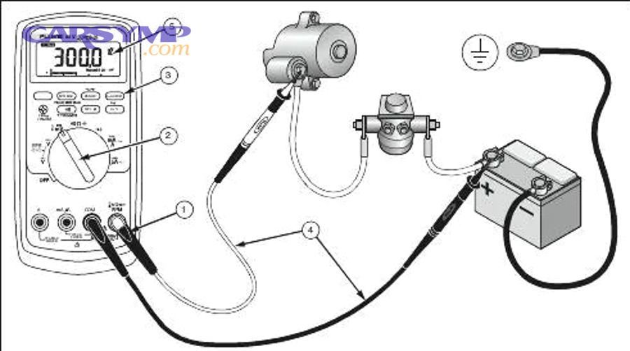
Solenoid testing begins with the component at rest. More specifically, you must disconnect the battery negative cable before testing resistance to prevent accidental starter engagement. The solenoid mounts on the starter motor housing or remotely on the firewall, depending on vehicle design. Identify the solenoid by locating the component with one large terminal connecting to the battery positive cable, a second large terminal connecting to the starter motor, and one or two small terminals for the control circuit.
How Do You Check Solenoid Continuity?
Solenoid continuity testing measures the electromagnetic coil’s resistance to verify it can generate sufficient magnetic force to operate the plunger mechanism. Disconnect all wires from the solenoid terminals and set your multimeter to the resistance (ohms) function. Touch one probe to the small control terminal and the other probe to the solenoid body or ground terminal. A functional solenoid coil measures 2-6 ohms of resistance, though exact values vary by manufacturer and solenoid design.
Infinite resistance (no continuity) indicates an open coil winding that cannot create the magnetic field needed to pull the plunger. This failure prevents the solenoid from engaging regardless of proper voltage supply. Zero or near-zero resistance suggests a shorted coil that may draw excessive current and burn out quickly, though it might work briefly before failing. Resistance values significantly outside the 2-6 ohm range warrant solenoid replacement.
Test the contact circuit by measuring resistance between the two large terminals on the solenoid. At rest, this should read infinite resistance (open circuit) because the contacts remain separated. Manually push the solenoid plunger if accessible, or use a jumper wire to energize the coil briefly. With the plunger engaged, resistance between the large terminals should drop to near zero (less than 0.1 ohms), indicating the contacts close properly. High resistance when engaged reveals burned or pitted contacts that create excessive heat and voltage drop during operation.
How Do You Test Solenoid Trigger Circuit Voltage?
Testing solenoid trigger voltage verifies the control circuit delivers sufficient power to energize the electromagnetic coil when you turn the ignition key to start. Reconnect the battery negative cable for this test, as the circuit requires power to function. Connect your multimeter’s black lead to a clean ground point and touch the red lead to the small control terminal on the solenoid where the trigger wire attaches.
With the multimeter in DC voltage mode, have an assistant turn the ignition key to the start position while you observe the reading. The control terminal should receive 12V (or within 1V of battery voltage) during the cranking attempt. This voltage flows through the ignition switch, neutral safety switch (automatic transmission) or clutch switch (manual transmission), and any starter relay in the circuit. Full voltage at this terminal confirms the control circuit functions properly.
If the control terminal receives no voltage, the problem exists upstream in the control circuit rather than in the solenoid itself. Common control circuit failures include:
- Faulty ignition switch: Internal contacts wear out, failing to complete the circuit in the start position
- Defective neutral safety switch: Prevents starting in park or neutral, or fails internally regardless of gear position
- Failed starter relay: Many vehicles use a relay to reduce current through the ignition switch, and relay contact failure blocks voltage to the solenoid
- Broken wiring: Trigger wires are small-gauge and break easily where they flex near hinges or rub against sharp edges
Trace the trigger circuit backward from the solenoid, testing voltage at each connection point until you find where 12V exists on one side but not the other. That identifies the failed component or broken wire section.
When the starter clicks but won’t start, the solenoid coil receives trigger voltage and energizes (creating the click sound), but the contacts fail to pass current to the motor. This symptom specifically indicates burned solenoid contacts or excessive resistance in the main power circuit. A single click diagnosis typically points to solenoid contact failure, while rapid clicks suggest insufficient voltage to fully energize the solenoid coil, usually from a dead battery.
How Do You Test Starter Motor Resistance?
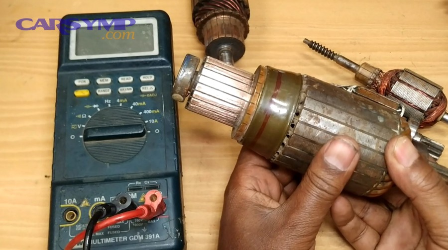
Test starter motor resistance by measuring armature winding resistance between the main terminal and motor housing (should read 0.05-0.2 ohms) and checking field coil resistance between the two field coil terminals (typically 0.2-0.6 ohms). These extremely low resistance values require a quality multimeter with milliohm precision and fresh batteries, as weak meter batteries produce inaccurate readings in the low-resistance ranges. Disconnect the battery before resistance testing to prevent accidental starter engagement during probe placement.
However, starter motor resistance testing presents challenges that limit its diagnostic value compared to voltage testing. The motor contains multiple current paths through armature windings, field coils, and brushes, creating complex resistance patterns. Additionally, the expected resistance values fall so low that test lead resistance (typically 0.2-0.5 ohms) can exceed motor winding resistance, making accurate measurements difficult without four-wire test methods.

What Resistance Values Indicate a Good Starter Motor?
A functional starter motor displays very low resistance values that reflect the heavy copper windings designed to carry hundreds of amperes during cranking. Specifically, the armature winding resistance typically measures 0.05-0.2 ohms when measured between the main positive terminal and the motor housing. This measurement includes resistance through the brushes, commutator, armature windings, and ground path through the motor frame.
Field coil resistance varies by motor design but generally measures 0.2-0.6 ohms between the field coil connections. Some starters use permanent magnets instead of electromagnetic field coils, making this measurement impossible. Check your vehicle’s service manual for exact specifications, as resistance values vary significantly between different starter motor designs, sizes, and manufacturers.
Resistance readings that indicate motor failure include:
- Infinite resistance (open circuit): Indicates broken winding wires, failed brush springs allowing brushes to lose contact with the commutator, or a completely worn commutator
- Near-zero resistance (short circuit): Suggests shorted windings where insulation has broken down, creating paths between winding loops that reduce motor power
- Inconsistent readings: Moving test probes or rotating the armature should produce stable readings; fluctuating values indicate intermittent connections in brushes or damaged commutator segments
To improve measurement accuracy, subtract test lead resistance from your readings. Touch your multimeter probes together and note the resistance reading (typically 0.2-0.5 ohms). Subtract this value from your starter motor measurements to determine actual motor resistance. For example, if probes show 0.3 ohms together and your motor measurement reads 0.4 ohms, the actual motor resistance equals 0.1 ohms.
How Do You Test for Ground Circuit Continuity?
Ground circuit continuity testing verifies the electrical return path from the starter motor housing back to the battery negative terminal functions properly. The starter motor mounts to the engine block, which connects to the chassis through ground straps, which finally connect to the battery negative terminal. Each connection point in this chain can develop resistance through corrosion, looseness, or physical damage.
Set your multimeter to continuity mode or the lowest resistance range (typically 200 ohms). Place one probe on the starter motor housing at a point you’ve cleaned to bare metal with a wire brush. Touch the other probe to the battery negative terminal. A good ground path reads less than 0.1 ohms resistance and triggers the continuity beeper. Higher resistance indicates ground path problems that starve the motor of current during cranking.
Common ground circuit failure points include:
- Engine block to chassis ground straps: These braided straps carry hundreds of amperes and deteriorate internally while appearing intact externally
- Battery negative cable connections: The cable terminals corrode at both the battery and chassis attachment points
- Starter mounting bolts: Paint, rust, or thread corrosion isolates the starter housing from the engine block ground
- Engine mount contact: Rubber engine mounts isolate the engine from the chassis electrically, requiring dedicated ground straps
When ground circuit resistance exceeds 0.1 ohms, inspect each connection point systematically. Remove ground strap bolts, clean contact surfaces to bare metal with a wire brush, apply dielectric grease, and reinstall with proper torque. Verify the battery negative cable shows no corrosion inside the terminal crimp where the cable insulation ends. Replace ground straps showing any fraying, discoloration from overheating, or broken wire strands.
The tap test myth suggests hitting the starter motor with a hammer can temporarily restore function in a failed starter. While this sometimes works, it indicates worn brushes that have stuck in their holders rather than a failed motor. Tapping jarrs the brushes back into contact with the commutator, creating temporary operation before they stick again. This symptom requires starter replacement, not continued hammering.
How Do You Interpret Multimeter Readings When Testing Starters?
Interpret multimeter readings by comparing measured values to specifications: battery voltage above 12.4V at rest and above 10.5V during cranking indicates adequate power, voltage drops below 0.2V on positive cables and 0.1V on ground cables confirm good connections, solenoid coil resistance of 2-6 ohms shows functional operation, and motor winding resistance of 0.05-0.2 ohms reflects normal condition. These benchmarks create decision points that guide diagnosis toward specific components or circuits requiring repair or replacement.
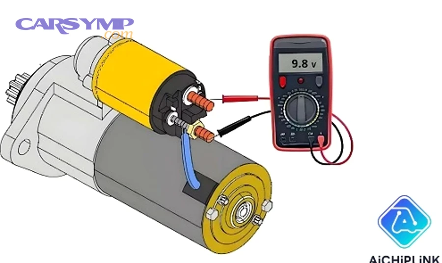
To illustrate, understanding what different readings mean helps you distinguish between similar symptoms with different root causes. For instance, a no-crank condition might result from a dead battery, failed starter motor, broken ground connection, or faulty ignition switch. Each cause produces a distinct pattern of multimeter readings that points to the specific failure.
What Do Different Voltage Readings Mean?
Voltage readings during starter testing create a diagnostic map that reveals circuit health at every measurement point. Each voltage value tells a story about current flow, resistance, and component condition. Interpreting these readings requires comparing them to expected values and understanding what deviations indicate.
| Measurement Point | Expected Reading | Low Reading Indicates | High Reading Indicates |
|---|---|---|---|
| Battery at rest | 12.4-12.7V | Discharged battery, sulfated plates, dead cell | Overcharged battery, bad voltage regulator |
| Battery during cranking | 10.5-11.5V | Weak battery, excessive current draw, cold temperature | No load (starter not engaging) |
| Starter terminal during cranking | Within 0.5V of battery voltage | Cable resistance, poor connections, corroded terminals | Good circuit (if battery voltage also high) |
| Solenoid trigger terminal | 12V when key in start position | Switch failure, broken wire, relay failure | Normal control circuit |
| Voltage drop positive cable | 0.2V or less | Normal operation | Poor connection, damaged cable |
| Voltage drop ground path | 0.1V or less | Normal operation | Poor ground, broken strap |
Specific diagnostic scenarios based on voltage patterns:
Battery reads 12.6V at rest but drops to 8V during cranking: This pattern indicates a battery with insufficient capacity to deliver the high current required for cranking. The battery has adequate voltage when no load is applied, but its internal resistance is too high. Recharge the battery and perform a load test, or replace if more than 3-4 years old.
Battery reads 11.0V during cranking, starter terminal reads 9.5V: The 1.5V difference exceeds the acceptable 0.5V limit, indicating excessive resistance in the positive cable circuit. Clean all connections between the battery positive terminal and starter motor terminal, including intermediate solenoid connections. Retest after cleaning.
Battery reads 11.0V during cranking, starter terminal reads 10.8V, but motor doesn’t spin: This pattern shows good voltage delivery to the starter (only 0.2V drop), but the motor fails to operate despite adequate power. The problem exists within the starter motor itself—likely burned solenoid contacts, seized bearings, or open motor windings.
Solenoid trigger terminal reads 0V when key turned to start: No voltage at the trigger terminal means the control circuit has failed upstream. The ignition switch, neutral safety switch, clutch switch, or starter relay has failed to complete the circuit. Trace backward to find where 12V exists before the failure point.
What Resistance Readings Indicate Starter Failure?
Resistance readings provide diagnostic value when voltage tests show adequate power delivery but the starter still fails to operate. These measurements identify internal starter component failures that prevent normal operation despite proper voltage supply. However, resistance values alone can’t diagnose all starter problems, as some failures only appear under load when the motor attempts to spin.
Infinite resistance readings (displayed as “OL” or “1” on digital multimeters) indicate open circuits within the starter. An infinite reading between the solenoid control terminal and ground shows an open coil winding that cannot energize the solenoid. Infinite resistance between the solenoid’s large terminals when the plunger is manually engaged reveals burned contacts that no longer make connection. Between the motor positive terminal and ground, infinite resistance points to open motor windings, failed brushes, or a completely worn commutator.
Zero or extremely low resistance (below 0.01 ohms) suggests short circuits that bypass normal current paths. Shorted motor windings draw excessive current, drain the battery quickly, and may cause the starter to spin weakly or not at all despite high current draw. Shorted solenoid coils pull excessive current through the control circuit, potentially burning out ignition switches or starter relays. These shorts generate significant heat, often producing burnt wire smells or visible damage to the starter housing.
Inconsistent or fluctuating resistance readings during testing reveal intermittent connections that cause unreliable starter operation. Rotating the armature while measuring resistance should produce stable readings if all internal connections are solid. Fluctuating values indicate worn brushes bouncing on the commutator, broken commutator segments, or loose internal connections. These intermittent failures explain starters that work sometimes but fail unpredictably.
What Are Common Starter Circuit Problems Found Through Multimeter Testing?
The most common starter circuit problems revealed through multimeter testing include discharged or failed batteries (accounting for approximately 40% of no-start conditions), corroded cable connections causing excessive voltage drop (30%), failed starter solenoids with burned contacts (15%), and worn starter motors with open windings or failed brushes (15%). Each problem creates a distinct pattern of multimeter readings that allows accurate diagnosis without unnecessary part replacement.
Besides identifying the specific failed component, multimeter testing differentiates between similar symptoms with different causes. A clicking sound during starting attempts might result from a weak battery, failed solenoid contacts, or a seized starter motor—three completely different problems requiring different solutions. Systematic voltage and resistance testing eliminates guesswork and prevents wasting money on unnecessary parts.
Is a Dead Battery the Most Common Cause of Starter Failure?
Yes, a dead or weak battery causes approximately 40-50% of all no-start conditions that appear to be starter failures, making it the single most common problem in the starting system. The battery must deliver 200-400 amperes during cranking, and even slight degradation reduces its ability to meet this demand. Cold weather compounds the problem, as battery capacity drops 30-50% at 0°F compared to 80°F, while engine oil thickens and increases cranking resistance.
However, distinguishing true battery failure from other problems requires proper testing rather than assumptions. Many people replace starters when batteries actually caused the problem, wasting hundreds of dollars on unnecessary repairs. Voltage testing definitively identifies battery problems before condemning the starter motor.
Test battery condition by measuring resting voltage after the battery sits unused for at least two hours. A reading above 12.4V indicates adequate charge level, while readings below 12.0V show a discharged battery requiring charging. After charging, retest voltage and perform a cranking voltage test. If battery voltage drops below 10.5V during cranking, either the battery has failed internally or excessive current draw exists in the circuit.
To distinguish between a weak battery and excessive current draw, perform a load test at an auto parts store or using a dedicated battery load tester. These devices apply a calibrated load equal to cranking current while measuring voltage drop. A good battery maintains above 9.6V during a 15-second load test at normal temperatures. Failed batteries show excessive voltage drop even when fully charged, indicating high internal resistance from sulfated plates or a dead cell.
According to data from the Battery Council International, the average automotive battery lifespan ranges from 3-5 years depending on climate and usage patterns. Batteries in hot climates (southern United States) typically fail after 3 years, while those in moderate climates last 4-5 years. Regular testing prevents unexpected failures and avoids misdiagnosing battery problems as starter failures.
Does a Bad Solenoid Show Specific Multimeter Readings?
Yes, a failed solenoid produces distinct multimeter readings that differentiate it from battery or motor problems: no voltage at the trigger terminal indicates control circuit failure, 12V at trigger terminal with infinite coil resistance shows an open coil, and 12V at trigger terminal with proper coil resistance but no cranking reveals burned contacts. These specific patterns allow confident solenoid diagnosis before replacement.
Solenoid contact failure creates the classic “single click but no crank” symptom. When you turn the key, you hear one loud click as the solenoid plunger engages, but the motor doesn’t spin. This happens because the electromagnetic coil works properly (creating the click sound), but the heavy contacts that complete the motor circuit have burned away, preventing current flow to the motor. Testing confirms this by measuring 12V at the solenoid trigger terminal and good coil resistance (2-6 ohms), but zero voltage reaching the starter motor terminal during cranking attempts.
Weak battery symptoms mimic solenoid failure but produce different test results. A weak battery causes rapid clicking as the solenoid repeatedly engages and disengages. This happens because the battery has enough power to energize the solenoid coil, but when the contacts close and the motor begins drawing current, battery voltage drops so low the coil can’t maintain the plunger position. The plunger releases, current stops, voltage recovers, the coil re-energizes, and the cycle repeats rapidly. Testing shows battery voltage dropping below 10V during the clicking, distinguishing this from true solenoid failure.
The table below compares symptoms and multimeter readings for different solenoid-related failures:
| Symptom | Trigger Voltage | Coil Resistance | Motor Voltage | Diagnosis |
|---|---|---|---|---|
| Single click, no crank | 12V | 2-6 ohms | 0V | Burned solenoid contacts |
| Rapid clicking | 12V | 2-6 ohms | Fluctuating | Weak battery |
| No click, no crank | 0V | 2-6 ohms | 0V | Control circuit failure |
| No click, no crank | 12V | Infinite | 0V | Open solenoid coil |
| Continuous engagement | 12V | 2-6 ohms | 12V continuous | Stuck solenoid plunger |
Replace the solenoid when testing confirms burned contacts or an open coil. Clean all connections and retest if control circuit problems appear, as poor connections often mimic component failures.
What Other Starting System Components Can You Test with a Multimeter?
Beyond the starter motor and solenoid, you can test ignition switches, starter relays, neutral safety switches, and battery cables using standard multimeter functions to diagnose the complete starting system. Each component plays a specific role in the control circuit that delivers power to the starter solenoid, and failures in any of these parts prevent starting despite a functional starter motor. Testing these components follows the same voltage and continuity principles used for starter testing.
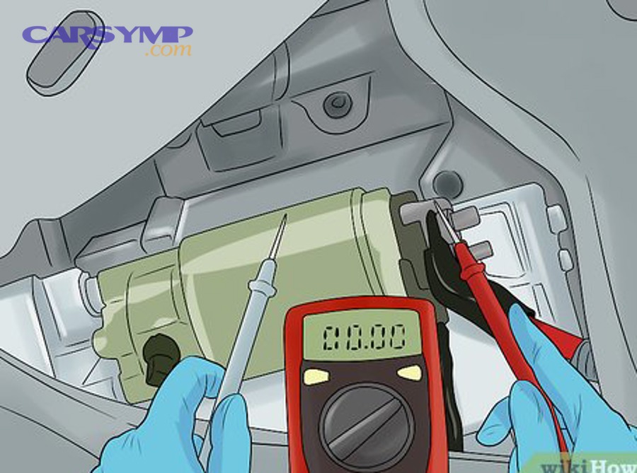
Especially important, many no-start conditions result from control circuit failures rather than starter motor problems. The starter motor itself is remarkably reliable compared to switches and relays that cycle thousands of times during the vehicle’s life. Understanding how to test these control components prevents unnecessary starter replacement and reduces diagnostic time.
How Do You Test the Ignition Switch with a Multimeter?
Test the ignition switch by measuring voltage at the switch output terminal in each key position, verifying continuity between the battery feed and appropriate output terminals as you rotate the key through Off, Accessory, On, and Start positions. The ignition switch routes battery power to different vehicle systems depending on key position, and internal contact wear causes intermittent or complete failure of the start circuit.
Access the ignition switch by removing the steering column covers to expose the switch body and wiring connector. Identify the wiring diagram for your specific vehicle to determine which terminals provide battery feed, accessory output, ignition output, and start output. Connect your multimeter’s black lead to ground and the red lead to the start circuit terminal on the switch.
With the key in the Off position, the start terminal should show zero voltage. Rotate the key to the Start position—the terminal should immediately receive 12V (battery voltage). If the start terminal receives no voltage when the key is in Start, the switch has failed internally. Some vehicles incorporate the neutral safety switch or clutch interlock into the ignition switch assembly, requiring proper gear position or clutch pedal depression before the switch completes the start circuit.
Test for voltage drops through the switch by measuring battery voltage at the input terminal while simultaneously measuring voltage at the start output terminal during a start attempt. Both measurements should be within 0.5V of each other. Greater voltage difference indicates high resistance in the switch contacts, reducing voltage delivered to the starter solenoid and potentially preventing engagement.
How Do You Test Starter Relay and Fuses?
Test starter relays by measuring coil resistance (typically 50-120 ohms), verifying contact continuity when the relay energizes, and confirming proper voltage at both the relay input and output terminals during start attempts. Many modern vehicles use a starter relay to reduce current through the ignition switch, protecting the switch from the high current required to energize the starter solenoid coil. This relay typically mounts in the under-hood fuse and relay box.
Locate the starter relay in the fuse box using the diagram printed on the cover or in your owner’s manual. Remove the relay by pulling it straight up from its socket. Identify the relay terminals—most automotive relays use a standard pin configuration with pins 85 and 86 for the coil, pin 30 for battery input, and pin 87 for the switched output to the starter solenoid.
Measure coil resistance by setting your multimeter to the 200-ohm range and touching probes to pins 85 and 86. Functional relay coils measure 50-120 ohms. Infinite resistance indicates an open coil that cannot energize the relay. Test contact operation by connecting a 12V power source to pins 85 and 86 while measuring continuity between pins 30 and 87. The relay should click audibly when energized, and continuity should appear between pins 30 and 87, confirming the contacts closed.
To test the relay in the circuit, reconnect it and measure voltage at pin 30 (should show constant 12V with battery connected) and pin 87 (should show 12V only when key is in Start position). No voltage at pin 87 when the key is in Start indicates either a failed relay or no trigger voltage arriving at the coil terminals from the ignition switch.
Starter circuit fuses rarely blow because the starter solenoid limits current once engaged. However, test fuse continuity by removing it from the holder and measuring resistance through the element (should read near zero ohms) or using the continuity function. A blown fuse reads infinite resistance and typically shows visible element damage. Replace only with the same amperage rating—oversized fuses eliminate protection against short circuits.
Can You Test the Neutral Safety Switch with a Multimeter?
Yes, you can test the neutral safety switch by verifying continuity between the switch terminals only when the transmission is in Park or Neutral, confirming zero continuity in all other gear positions. This switch prevents starter engagement when the transmission is in gear, protecting against vehicle movement during starting. Failed neutral safety switches cause no-start conditions despite properly functioning starters, batteries, and control circuits.
The neutral safety switch mounts either on the transmission case near the shift linkage or inside the steering column as part of the shift mechanism. Locate the switch and disconnect its electrical connector. Set your multimeter to continuity mode and touch probes to the switch terminals. With the transmission in Park, the switch should show continuity (beep on the meter). Shift to Neutral—continuity should remain. Shift to Reverse, Drive, or any forward gear—continuity should disappear (no beep).
If the switch shows continuity in Drive or fails to show continuity in Park and Neutral, it requires adjustment or replacement. Many switches include adjustment slots that allow repositioning to align with the shift mechanism. Loosen the mounting bolts, shift to Neutral, adjust the switch until continuity appears, then tighten the bolts and retest through all gear positions.
Manual transmission vehicles use a clutch safety switch instead of a neutral safety switch. This switch mounts near the clutch pedal and completes the start circuit only when the pedal is fully depressed. Test it using the same continuity method—the switch should show continuity only when the clutch pedal is pressed to the floor. No continuity with the pedal depressed indicates a failed switch or misadjusted mounting position.
What Is the Difference Between Testing Starter Motor vs Alternator with a Multimeter?
Testing starter motors focuses on DC voltage delivery, very low resistance measurements, and high-current circuit integrity, while alternator testing measures AC ripple voltage, higher resistance values, and voltage regulation under varying loads. Though both are rotating electrical machines in the automotive system, they perform opposite functions—the starter converts electrical energy to mechanical rotation, while the alternator converts mechanical rotation to electrical energy.
Starter testing uses the 0-20V DC range to measure battery voltage, voltage drops, and solenoid trigger voltage. All starter circuit voltages are DC (direct current) from the battery. Resistance measurements fall in the milliohm range (0.05-0.2 ohms for motor windings) because the starter uses heavy conductors to carry hundreds of amperes. Testing focuses on whether adequate voltage reaches the motor and whether connections maintain low resistance under high current flow.
Alternator testing requires different multimeter functions and voltage ranges. Measure alternator output voltage at the battery terminals with the engine running (should read 13.5-14.5V), indicating proper voltage regulation. Test for AC ripple by switching the multimeter to AC voltage mode while connected to the battery—readings above 0.5V AC indicate failing alternator diodes that aren’t fully converting AC to DC. Alternator field coil resistance typically measures 2-6 ohms, similar to starter solenoid coils, but serves the different purpose of creating the magnetic field needed for power generation.
Key differences in testing approach:
- Current flow direction: Starter motor receives current from the battery; alternator supplies current to the battery
- Voltage ranges: Starter operates at battery voltage (12V); alternator generates 13.5-14.5V to charge the battery
- Resistance values: Starter motor windings measure 0.05-0.2 ohms; alternator stator windings measure 0.2-1.0 ohms
- Testing conditions: Starter testing occurs with engine off during cranking; alternator testing requires running engine at various RPMs
- AC vs DC: Starter circuits are purely DC; alternators generate AC internally that’s converted to DC output
Understanding these differences prevents confusion when diagnosing electrical problems and ensures proper multimeter setup for each component type.