


A bad ground cable is the root cause of click-no-start issues in approximately 15-20% of all starting system failures, yet it remains one of the most overlooked electrical problems. When you turn your ignition key and hear a single click or rapid clicking sound without the engine cranking, a compromised ground cable creating excessive electrical resistance is likely preventing sufficient current from reaching your starter motor. This diagnostic guide walks you through identifying, testing, and repairing ground cable issues using tools and methods accessible to home mechanics.
Recognizing the seven key symptoms of ground cable failure helps you differentiate this problem from similar issues like dead batteries, faulty starters, or bad alternators. These symptoms include characteristic clicking sounds during start attempts, dramatic headlight dimming, intermittent starting behavior, visible corrosion at connection points, warm ground cables during operation, successful starts when using jumper cable bypasses, and multiple simultaneous electrical malfunctions. Understanding these indicators allows you to quickly narrow down the source of your starting problem.
Testing a ground cable requires three straightforward methods that confirm whether resistance in the ground path is causing your no-start condition. The visual inspection identifies obvious corrosion and loose connections, the jumper cable bypass test proves ground path failure by creating an alternate route, and the voltage drop test with a multimeter quantifies exactly how much resistance exists in your ground circuit. Each testing method provides specific diagnostic information that guides your repair approach.
Fixing ground cable problems ranges from simple terminal cleaning to complete cable replacement, with costs varying from nearly nothing for DIY cleaning to $15-50 for replacement cables. To begin, let’s examine exactly what a ground cable does in your vehicle’s electrical system and why its failure creates that distinctive clicking sound without engine cranking.
What Is a Ground Cable and Why Does It Cause Click-No-Start Issues?
A ground cable is the heavy-gauge wire that creates the return electrical path from your vehicle’s chassis and engine block back to the battery’s negative terminal, completing the circuit necessary for all electrical functions. This cable serves as the foundation for your entire electrical system, carrying hundreds of amps during starter motor operation and providing the reference point for all electrical measurements in your vehicle.
To better understand this critical component, let’s explore how it functions within your starting system and what happens when it fails.
How Does a Ground Cable Work in Your Car’s Starting System?
The ground cable completes a high-current loop that begins at your battery’s positive terminal, travels through the ignition switch and starter solenoid to the starter motor, then returns through the engine block and ground cable back to the battery’s negative terminal. When you turn your ignition key, the starter solenoid closes, allowing 150-400 amps of current to flow from the battery positive terminal through heavy-duty cables to the starter motor. The starter motor uses this massive current draw to generate the torque needed to rotate your engine’s flywheel and initiate combustion.
For this circuit to function properly, the ground path must provide equally low resistance as the positive path. The ground cable typically connects in two critical locations: one heavy cable runs from the battery negative terminal to the vehicle’s chassis or frame rail, and a second cable connects the engine block to the chassis. This dual-ground configuration ensures that current can flow freely from the starter motor (mounted on the engine) back through the engine block, through the engine-to-chassis ground strap, across the chassis, and finally through the battery ground cable back to the battery’s negative terminal.
Every connection point in this ground path—the battery terminal clamp, the chassis mounting bolt, the engine block attachment point, and the engine-to-chassis strap—must maintain metal-to-metal contact with minimal resistance. Paint, corrosion, rust, or loose connections at any point create resistance that impedes current flow. Since the starter motor requires such high current, even a small amount of resistance (measured in fractions of an ohm) can prevent adequate current from completing the circuit.
What Happens When a Ground Cable Fails?
When resistance develops in your ground cable or its connections, the electrical circuit cannot support the high amperage needed for starter motor operation, resulting in the characteristic click-no-start condition. The starter solenoid still receives enough current through its control circuit to engage and produce an audible click, but the starter motor itself cannot draw sufficient current to generate rotational torque. This creates a situation where the solenoid clicks repeatedly as it tries to engage, immediately loses voltage due to the ground resistance, disengages, then tries again in rapid succession.
The failure mechanism typically occurs in three ways. First, corrosion develops at the connection points where copper cable meets steel chassis or aluminum engine block. When dissimilar metals contact each other in the presence of moisture and road salt, galvanic corrosion creates a resistive layer of oxide that acts as an insulator. Second, the copper strands inside the cable insulation can break down over time due to vibration, flexing, and exposure to heat from the engine. These broken strands remain hidden inside intact-looking insulation but reduce the cable’s current-carrying capacity. Third, the terminal clamps can loosen over time from thermal expansion and contraction cycles, creating intermittent high-resistance connections.
When the starter tries to draw current through a high-resistance ground path, the available voltage at the starter motor drops below the 9-10 volts minimum required for operation. Your battery may measure a healthy 12.6 volts when tested with no load, but during cranking attempts, the voltage at the starter drops to 6-7 volts or lower due to the voltage drop across the resistive ground connection. This voltage drop follows Ohm’s Law: voltage drop equals current multiplied by resistance (V = I × R). With 200 amps attempting to flow through a ground connection that has developed even 0.05 ohms of resistance, you lose 10 volts (200A × 0.05Ω = 10V), leaving insufficient voltage for starter operation.
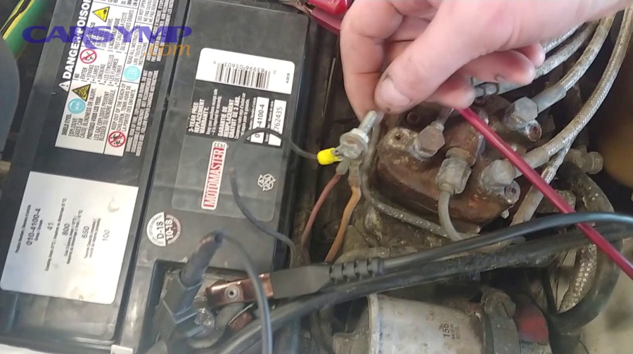
The click sound you hear originates from the starter solenoid—an electromagnetic switch that physically moves a plunger to engage the starter motor’s drive gear with your engine’s flywheel. This solenoid requires only 3-5 amps through its control circuit to activate, which easily flows even through a degraded ground path. However, once the solenoid engages and the main starter circuit attempts to draw 150-400 amps, the voltage collapse caused by ground resistance prevents the solenoid from staying engaged, creating the rapid clicking pattern as it cycles on and off.
Is a Bad Ground Cable Causing Your Click-No-Start Problem?
Yes, a bad ground cable causes click-no-start problems when seven specific symptoms appear: single or rapid clicking during start attempts, dramatic headlight dimming, successful starts with jumper cables to the engine block, intermittent starting that worsens when hot, visible corrosion at cable connections, warm or hot ground cables during operation, and multiple simultaneous electrical malfunctions.

Identifying these symptoms helps you confirm ground cable failure before investing time and money in unnecessary starter or battery replacements. Let’s examine each symptom in detail and understand how to differentiate ground cable issues from other starting system problems.
What Are the 7 Key Symptoms of a Bad Ground Cable?
Symptom 1: Single Click or Rapid Clicking When Turning the Key
When you turn your ignition key and hear one loud click followed by silence, or a rapid machine-gun-like clicking sound, your starter solenoid is engaging but cannot maintain engagement due to insufficient current flow through a resistive ground path. The single click indicates the solenoid activated once, pulled in the starter drive gear, but immediately dropped out when voltage collapsed under load. Rapid clicking occurs when the solenoid repeatedly tries to engage in quick succession—clicking 3-10 times per second—as voltage momentarily recovers between engagement attempts then drops again when current tries to flow.
This clicking pattern differs from the labored “rrrr-rrrr-rrrr” grinding sound of a weak battery attempting to slowly crank the engine, and it differs from complete silence which indicates no power reaching the starter circuit at all. The click specifically indicates that your control circuit has sufficient power to activate the solenoid electromagnet, but the main high-current circuit cannot support starter motor operation.
Symptom 2: Headlights Dim Dramatically During Start Attempts
Your headlights dimming to near-complete darkness when you attempt to start the engine reveals excessive voltage drop somewhere in your starting circuit. When you turn the key with headlights on, watch carefully—if the lights dim from bright white to deep orange or nearly go out completely, then return to normal brightness when you release the key, your electrical system is experiencing severe voltage drop under the starter load. This occurs because the headlights and starter share the same 12-volt electrical system, and when ground resistance prevents current from flowing efficiently through the starter circuit, the voltage available throughout the entire electrical system drops dramatically.
A healthy starting system will show slight headlight dimming during cranking—perhaps 20-30% reduction in brightness—but the lights should remain clearly visible. When ground cable resistance causes voltage to drop below 9 volts system-wide, headlights can dim by 70-90% or extinguish completely. This dramatic dimming combined with clicking sounds strongly indicates ground path resistance rather than a weak battery, which would cause slow cranking with moderate dimming.
Symptom 3: Car Starts When Jumper Cable Connects Battery Negative to Engine Block
The most definitive diagnostic symptom occurs when connecting a jumper cable from your battery’s negative terminal directly to a clean metal point on the engine block allows the vehicle to start normally, bypassing your existing ground cable. This test creates an alternate low-resistance ground path that proves your original ground cable or its connections have developed excessive resistance. When you hook up the jumper cable and the engine immediately cranks and starts, you’ve confirmed that power, starter motor, and all other components work properly—only the ground return path was faulty.
Specifically, when the jumper cable provides a good ground connection directly to the engine where the starter mounts, current can flow from the starter motor case through the jumper cable directly back to the battery negative terminal without traveling through the corroded or broken original ground cable. This bypass eliminates the resistance that was preventing starter operation. If the vehicle still won’t start even with a jumper cable providing an engine ground, your problem lies elsewhere—possibly in the starter itself, the positive battery cable, or the ignition switch circuit.
Symptom 4: Intermittent Starting That Works When Cold but Fails When Hot
When your vehicle starts reliably on cold mornings but refuses to start after reaching operating temperature or on hot afternoons, thermal expansion at corroded connection points is likely increasing ground resistance. Metal expands when heated, and if corrosion exists at the battery terminal, chassis mount, or engine block connection, this expansion can break marginal metal-to-metal contact that barely worked when cold. The resistance that was borderline acceptable at 0.03 ohms when cold might increase to 0.08 ohms when hot, crossing the threshold where starter operation becomes impossible.
This temperature-dependent failure pattern also occurs because electrical resistance in copper increases with temperature—a hot cable has approximately 20% higher resistance than a cold cable. When you combine the natural temperature-related resistance increase with thermal expansion breaking contact at corroded connection points, you get a failure mode that specifically manifests when the vehicle is hot. Drivers often misdiagnose this as a failing starter motor because starter motors can also fail more frequently when hot, but the jumper cable test immediately distinguishes between these two causes.
Symptom 5: Visible Corrosion on Cable Ends or Connection Points
Green, white, or blue crusty buildup at your battery terminals, ground cable ends, or chassis connection points indicates active corrosion creating electrical resistance. Copper corrosion appears as a blue-green patina, while battery terminal corrosion typically shows as white or light blue crusty deposits. This corrosion forms when copper or lead comes into contact with moisture and acidic battery fumes, creating copper sulfate, lead sulfate, or copper oxide compounds that act as electrical insulators.
When you visually inspect your ground cable connections and see corrosion, check specifically at these points: the negative battery terminal clamp where it grips the battery post, the cable lug where it bolts to the chassis or engine block, and the braided strap connections if your vehicle uses a separate engine-to-chassis ground strap. Even if the cable itself looks fine, corrosion at the connection points creates the high resistance responsible for click-no-start symptoms. Some vehicles have ground connections hidden under components or covered by protective boots, requiring more thorough inspection to locate corroded connections.
Symptom 6: Ground Cable Feels Warm or Hot During Operation
A ground cable that feels warm to the touch after driving or attempting to start indicates current flowing through excessive resistance, converting electrical energy into heat. In a healthy ground circuit with minimal resistance, the cable should remain cool or only slightly warm even during heavy electrical loads. When resistance develops within the cable or at its connections, the mathematical relationship P = I²R (power dissipation equals current squared times resistance) means that high starter current flowing through even small resistance generates substantial heat.
For example, if your ground cable has developed 0.1 ohms of resistance and 200 amps attempts to flow through it during cranking, the power dissipation equals 200² × 0.1 = 4,000 watts of heat energy—enough to make the cable noticeably hot within seconds. This heat often concentrates at the specific point of highest resistance, such as a corroded terminal connection, causing that area to become particularly hot. If you notice heat at the battery terminal clamp, that clamp has excessive resistance; if the heat appears at the chassis mounting point, corrosion or a loose connection exists there.
Symptom 7: Multiple Electrical Accessories Malfunctioning Simultaneously
When your ground cable develops resistance, it affects not only starting but all electrical components that rely on chassis ground for their return path, causing seemingly unrelated electrical problems to appear together. You might notice flickering dashboard lights, dim headlights during low-speed driving, radio cutting in and out, power windows operating slowly, or warning lights illuminating intermittently—all symptoms of inadequate grounding affecting multiple circuits simultaneously.
This multi-system failure pattern occurs because most vehicle electrical accessories ground to the chassis at various points, and all ultimately depend on the main battery ground cable to complete their circuits back to the battery negative terminal. When the main ground cable has high resistance, every electrical component experiences voltage reference problems and inadequate current return paths. The severity of symptoms varies among components based on their current requirements—high-current devices like headlights and blower motors show more obvious problems than low-current devices like radio memory circuits.
How Is This Different from a Bad Starter or Dead Battery?
Understanding the differences between bad ground cable symptoms, dead battery symptoms, and bad starter symptoms prevents misdiagnosis and unnecessary parts replacement. The following comparison table clarifies the distinctive characteristics of each condition:
| Symptom | Bad Ground Cable | Dead Battery | Bad Starter | Bad Alternator |
|---|---|---|---|---|
| Key turn response | Single click or rapid clicking | Slow cranking or nothing | Single click or grinding noise | Normal starting |
| Headlight behavior | Extreme dimming (70-90%) during start attempt | Dim continuously, even without starting | Moderate dimming (20-40%) during failed start | Dim while driving at low RPM |
| Jumper to engine test | Starts normally with jumper cable ground | Starts normally with jump from another battery | No improvement with jumper to engine | N/A (not a starting issue) |
| Voltage at battery | 12.4-12.6V with key off | Below 12.0V with key off | 12.4-12.6V with key off | Below 13.5V while running |
| Consistency | Often intermittent, worse when hot | Consistent failure until charged | May fail intermittently or consistently | Affects battery charge over hours/days |
| Electrical accessories | Multiple systems affected | Radio/lights weak or non-functional | Accessories work normally | Battery warning light on |
The key differentiator involves the jumper cable test: connecting a jumper from battery negative directly to the engine block solves bad ground problems immediately but has no effect on bad starter or dead battery problems. A truly dead battery requires a jump from another battery’s positive and negative terminals to provide the necessary voltage and capacity for starting. A bad starter won’t crank even with perfect power and ground connections, though it may still click.
When diagnosing, use a multimeter to check battery voltage with the key off—it should read 12.4-12.6 volts for a healthy charged battery. If voltage reads 12.0V or lower, charge or replace the battery before diagnosing further. If battery voltage is good but the starter clicks but won’t start, measure voltage at the starter motor’s main terminal while someone attempts to crank the engine. If voltage drops below 9.5 volts during cranking, you have excessive resistance somewhere in the circuit—most commonly in the ground path.
How Do You Test a Ground Cable to Confirm It’s Bad?
Testing a ground cable involves three progressive methods—visual inspection of all ground connections, jumper cable bypass testing to confirm ground path failure, and voltage drop measurement with a multimeter to quantify resistance—that together provide definitive diagnosis within 15-30 minutes using basic tools.
Each testing method reveals different aspects of ground cable condition, from obvious physical damage to hidden internal degradation. Let’s examine each test in detail so you can systematically confirm whether ground resistance causes your starting problem.
How to Perform a Visual Inspection of Ground Cables
Start your diagnosis by locating and visually examining every ground connection point in your vehicle’s electrical system, beginning with the battery negative terminal and following the cables to their chassis and engine attachment points. Open your hood and identify the heavy black cable attached to your battery’s negative post—this is your primary battery ground cable. Follow this cable to where it bolts to the vehicle’s chassis, inner fender, or frame rail, typically within 12-24 inches of the battery.
Next, locate the engine-to-chassis ground strap, which is usually a braided copper cable 6-12 inches long connecting the engine block to the vehicle’s chassis or inner fender. On front-wheel-drive vehicles, this strap often runs from the transmission bell housing to the chassis. On rear-wheel-drive vehicles, it typically connects from the engine block near the rear of the engine to the firewall or frame. Some vehicles have multiple engine ground straps for redundancy.
Inspect each connection point for these specific signs of failure:
- Corrosion at battery terminal: Look for white, blue, or green crusty deposits where the cable clamp grips the battery post, or around the clamp’s bolt. This corrosion creates resistance between the cable and battery.
- Corroded cable ends: Examine where the cable attaches to the chassis or engine block. The cable should be secured with a bolt through a metal terminal lug. Check for corrosion between the lug and the mounting surface, or on the bolt threads.
- Frayed or damaged cable insulation: Run your hand along the entire length of each ground cable checking for cracks, cuts, or abraded areas in the rubber insulation. Damaged insulation exposes copper strands to moisture, causing internal corrosion.
- Green discoloration of copper: If insulation damage exposes the copper strands, look for green oxidation on the copper itself. Copper oxide is an insulator that increases resistance.
- Loose connections: Try wiggling the battery terminal clamp and the chassis/engine mounting bolts. They should be completely tight with no movement. Loose connections create intermittent high resistance.
- Oil or fluid contamination: Check if engine oil, transmission fluid, or power steering fluid has leaked onto ground cables. Some fluids degrade cable insulation over time.
Pay particular attention to ground connections located in areas exposed to road spray, such as lower chassis mounting points near the front wheels. These locations accumulate salt in winter climates, accelerating corrosion. Also check connections in the engine compartment that experience high heat, as thermal cycling degrades connections faster.
If you find visible corrosion, damage, or loose connections, you’ve identified the likely source of your ground problem. However, a cable can pass visual inspection yet still have internal degradation—broken copper strands hidden inside intact insulation—which is why functional testing remains necessary.
How to Do a Jumper Cable Bypass Test
The jumper cable bypass test definitively proves whether ground path resistance causes your no-start condition by creating an alternate low-resistance ground connection that bypasses your existing ground cable. To perform this test, you’ll need a set of jumper cables and access to a clean metal point on your engine block.
Follow these steps carefully to execute the bypass test safely:
Step 1: Preparation and Safety
Ensure your vehicle is in Park (automatic) or Neutral (manual) with the parking brake firmly engaged. Turn off all electrical accessories including lights, radio, and climate control to reduce electrical load during testing. Put on safety glasses to protect against potential battery sparks.
Step 2: Locate a Good Engine Ground Point
Identify a clean, unpainted metal surface on your engine block for the jumper cable connection. Good locations include:
- Engine lifting hooks or eyebolts (usually found at the front and rear of the engine)
- Alternator mounting brackets
- Starter motor mounting bolts
- Engine block casting surfaces (avoid painted, plastic, or rubber surfaces)
If the surface shows paint, oil, or dirt, clean it with a wire brush or sandpaper to expose bare metal. The connection quality directly affects test accuracy.
Step 3: Connect the Jumper Cable
Take one jumper cable and connect one clamp firmly to your battery’s negative terminal (the terminal with the existing black ground cable attached). Route the jumper cable to your chosen engine ground point, keeping it away from moving parts like belts and fans. Attach the other clamp securely to the clean metal surface on the engine block, ensuring the clamp teeth bite into the metal for good contact.
Step 4: Attempt to Start the Vehicle
With the jumper cable creating a direct ground path from battery to engine, turn the ignition key and attempt to start the vehicle. Observe what happens:
- If the engine cranks and starts normally: Your original ground cable or connections have excessive resistance. The jumper cable provided the low-resistance path needed for proper starter operation, confirming ground cable failure.
- If you still hear only clicking without cranking: Either your jumper cable connection isn’t making good contact (try repositioning the clamp), or your problem isn’t ground-related. Check that the clamp firmly grips bare metal.
- If nothing happens at all: The problem likely isn’t in the ground path. Investigate the positive battery cable, starter motor, or ignition switch circuit.
Step 5: Verify Results
If the vehicle started with the jumper cable attached, turn it off and remove the jumper cable. Attempt to start again without the jumper—the original clicking should return, confirming that the jumper cable was providing the necessary ground that your original cable couldn’t provide.
Safety Notes:
Never touch both jumper cable clamps together while connected to the battery, as this creates a direct short circuit. Keep the jumper cable away from the serpentine belt and any moving engine components. If you see sparks, smoke, or smell burning when connecting the jumper cable, immediately disconnect it—these indicate a serious electrical short elsewhere in the system.
The bypass test works because it provides a known good ground connection using fresh cable with clean connections at both ends. This isolates the ground path as the variable being tested. When the bypass eliminates the problem, you’ve confirmed that resistance in your permanent ground cable installation causes the no-start condition.
How to Perform a Voltage Drop Test with a Multimeter
The voltage drop test with a digital multimeter provides precise quantitative measurement of resistance in your ground circuit, revealing exactly how much voltage is lost to resistance during starter operation. This test identifies marginal ground connections that might pass visual inspection and even work intermittently, giving you objective data about ground circuit condition.
Required Tools and Meter Settings
You’ll need a digital multimeter (DMM) capable of measuring DC voltage in the 0-20 volt range. Set your multimeter to the DC voltage (DCV) setting, typically at the 20V range. Most multimeters have red and black test leads—red for positive connections and black for negative/ground connections. An assistant to operate the ignition key while you hold meter probes makes this test much easier.
Testing Procedure
The voltage drop test measures the voltage difference between two points in the ground circuit while current flows during a cranking attempt. Any voltage difference indicates resistance creating a voltage drop according to Ohm’s Law (V = I × R). In a perfect ground circuit with zero resistance, you would measure zero voltage drop. In reality, some small voltage drop is acceptable, but excessive voltage drop indicates problems.
Test 1: Battery Negative Terminal to Chassis Ground Point
Connect your meter’s black lead to the battery negative terminal (the terminal post itself, not the cable clamp). Connect the red lead to a clean metal point on the chassis or frame where your battery ground cable attaches. Have your assistant turn the ignition key to attempt cranking while you observe the multimeter reading. The meter will show the voltage drop across the battery ground cable during current flow.
- Acceptable result: 0.0-0.2 volts drop
- Marginal result: 0.2-0.4 volts drop (cable and connections starting to degrade)
- Failed result: 0.4+ volts drop (excessive resistance requiring repair)
If you measure more than 0.4 volts drop, significant resistance exists either in the cable itself or at the battery terminal or chassis mounting point. This resistance is preventing adequate current flow to the starter.
Test 2: Engine Block to Battery Negative Terminal
Connect the meter’s black lead to a clean metal point on the engine block near the starter motor. Connect the red lead to the battery negative terminal. Have your assistant attempt cranking while you read the meter. This test measures the total voltage drop in the complete ground return path from engine to battery, including the engine-to-chassis ground strap, chassis ground cable, and all connection points.
- Acceptable result: 0.0-0.3 volts drop
- Marginal result: 0.3-0.5 volts drop
- Failed result: 0.5+ volts drop
Higher voltage drop in this test compared to Test 1 indicates resistance in the engine-to-chassis ground strap or its connections. The difference between Test 1 and Test 2 results shows you where to focus repair efforts.
Test 3: Engine Block to Chassis Ground Point
For vehicles with a separate engine-to-chassis ground strap, connect the black lead to the engine block and the red lead to the chassis point where the ground strap attaches. This isolates the engine ground strap itself.
- Acceptable result: 0.0-0.1 volts drop
- Failed result: 0.1+ volts drop
This test specifically evaluates the braided ground strap that many mechanics overlook. These straps corrode internally or break strands due to engine vibration and movement.
Interpreting Results and Resistance Calculation
Your multimeter reading during cranking shows the voltage drop across the ground path. To calculate actual resistance, use Ohm’s Law: R = V / I (resistance equals voltage divided by current). If you measure 0.5 volts drop and your starter draws 200 amps, the resistance is 0.5V ÷ 200A = 0.0025 ohms. While this seems small, at 200 amps it creates a 0.5-volt drop—enough to significantly impair starter operation.
Professional mechanics consider the entire ground circuit from starter case to battery negative terminal should have less than 0.05 ohms total resistance. Each connection point should contribute less than 0.01 ohms. When you measure voltage drop exceeding these thresholds, you’ve identified excessive resistance requiring correction.
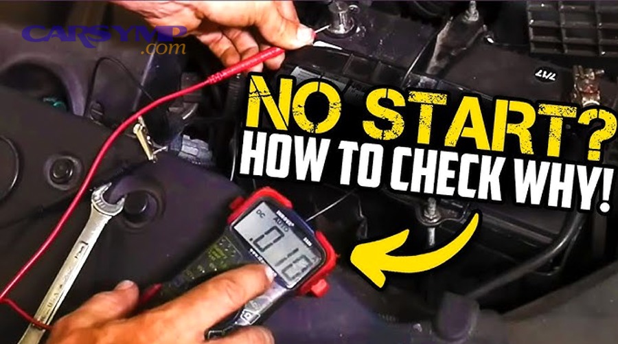
According to automotive electrical system standards established by the Society of Automotive Engineers (SAE), total voltage drop in a 12-volt starting circuit should not exceed 0.5 volts on the ground side during cranking. Measurements exceeding this threshold indicate excessive resistance that can prevent reliable starting, particularly in cold weather when starter current requirements increase by 30-50%.
What Are the Best Fixes for a Bad Ground Cable?
Fixing a bad ground cable involves three approaches ranked by effectiveness: cleaning and restoring corroded connections (effective for 40-50% of cases), complete cable replacement (necessary for internal degradation or severe damage), and adding supplementary ground cables for enhanced reliability (recommended for high-performance or high-electrical-load vehicles).

The repair method you choose depends on your voltage drop test results, the physical condition of your cables, and whether you experienced intermittent or complete failure. Let’s explore each fix in detail with step-by-step procedures.
How to Clean and Restore Corroded Ground Cable Connections
Cleaning corroded ground connections restores proper electrical contact when your cables remain structurally sound but have developed surface corrosion at battery terminals or mounting points. This repair costs virtually nothing and takes 20-30 minutes, making it the ideal first step before considering cable replacement.
Tools and Materials Needed:
- Wire brush or battery terminal cleaning brush
- Baking soda (sodium bicarbonate)
- Water in a spray bottle
- Wrench or socket set matching your battery terminal and ground bolt sizes
- Sandpaper or emery cloth (120-220 grit)
- Protective gloves and safety glasses
- Dielectric grease or petroleum jelly
- Clean rags
Cleaning Procedure:
Step 1: Disconnect the Battery
Always disconnect the negative battery cable first by loosening the terminal clamp bolt and removing the clamp from the battery post. This prevents accidental shorts during cleaning. Set the cable aside so it cannot touch the battery post.
Step 2: Prepare Cleaning Solution
Mix 1 tablespoon of baking soda with 8 ounces of water in your spray bottle. This alkaline solution neutralizes acidic battery corrosion and makes it easier to remove.
Step 3: Clean the Battery Terminal and Cable Clamp
Spray the baking soda solution generously on the battery negative post and the cable clamp. You’ll see fizzing and bubbling as the baking soda neutralizes acid. Let it sit for 2-3 minutes, then scrub the battery post with a wire brush using circular motions until you see shiny, clean metal. Use the battery terminal brush (which has both internal and external brushes) to clean inside the cable clamp. Scrub until all corrosion is removed and the metal shines.
Rinse both the post and clamp with clean water, then dry thoroughly with a rag. Any remaining moisture will cause corrosion to return quickly.
Step 4: Clean the Chassis and Engine Ground Points
Locate where your ground cable(s) bolt to the chassis and engine block. Remove the bolt(s) securing each ground connection using the appropriate wrench or socket. Remove the cable terminal lug(s). Inspect the mounting surface on the chassis or engine block—it should be clean, bare metal. If you see paint, rust, or corrosion, use sandpaper or emery cloth to remove it, exposing bright metal. Similarly, sand both sides of the cable terminal lug until shiny. The bolt threads should also be clean—use a wire brush to remove any corrosion or thread compound.
Step 5: Reassemble Connections
Before reinstalling, apply a thin coat of dielectric grease or petroleum jelly to the battery post, cable clamp interior, and chassis/engine mounting surfaces. This grease prevents future corrosion by excluding moisture and air from the metal contact surfaces. Reinstall the cable terminal lugs at chassis and engine mounting points, ensuring the lugs sit flat against bare metal. Tighten the mounting bolts firmly—typically to 10-15 ft-lbs torque, though check your vehicle’s service manual for specifications.
Reconnect the cable clamp to the battery negative post, ensuring it seats completely onto the post. Tighten the clamp bolt firmly, but don’t overtighten as this can crack the clamp. Apply a small amount of grease on top of the connection to seal out moisture.
When Cleaning Is Sufficient vs. When Replacement Is Needed
Cleaning successfully restores ground connections when corrosion exists only on the surfaces of connection points and the cable itself remains intact. After cleaning and reassembly, perform the voltage drop test again. If voltage drop now falls within acceptable limits (under 0.2-0.3 volts), your cleaning succeeded and no further repair is necessary.
However, cleaning cannot fix these conditions requiring replacement:
- Green or black discoloration extending into the cable insulation (indicates internal copper corrosion)
- Broken or frayed cable strands visible through damaged insulation
- Cable that feels stiff or inflexible (indicates internal strand breakage)
- Cable that shows heat damage (melted, charred, or hardened insulation)
- Voltage drop test showing continued high resistance after thorough cleaning
- Physical damage from contact with moving parts or excessive bending
If you see any of these signs, or if cleaning fails to reduce voltage drop to acceptable levels, proceed to cable replacement.
How to Replace a Ground Cable (Step-by-Step)
Complete ground cable replacement becomes necessary when internal cable degradation, severe corrosion, or physical damage prevents adequate current flow even after cleaning all connections. Replacement ensures reliable long-term performance and typically costs $15-50 for parts plus 30-60 minutes of your time.
Tools and Parts Needed:
- Replacement ground cable(s) matching your vehicle’s requirements
- Wrench or socket set for battery terminals and mounting bolts
- Wire cutters/strippers (if customizing cable length)
- Crimping tool (if installing custom terminals)
- Dielectric grease
- Safety glasses and gloves
Selecting the Correct Replacement Cable
Ground cables are specified by three critical parameters: gauge (wire thickness), length, and terminal configuration. Your replacement cable must match all three specifications to function properly.
Cable Gauge: Automotive ground cables typically use 2-gauge, 1-gauge, or 0-gauge wire, with lower numbers indicating thicker wire capable of carrying more current. Most passenger vehicles use 4-gauge or 2-gauge cable for the main battery ground. Larger vehicles, diesels, or vehicles with high-output electrical systems may use 1-gauge or 0-gauge. Check your original cable—it should have the gauge stamped on the insulation. When in doubt, measure the cable diameter: 4-gauge measures approximately 0.23 inches (5.8mm), 2-gauge measures 0.29 inches (7.4mm), 1-gauge measures 0.33 inches (8.4mm).
Never replace a ground cable with a smaller gauge (higher number) than original. Using an undersized cable creates excessive resistance. Using one gauge size larger than original is acceptable and provides a small performance improvement.
Cable Length: Measure your existing cable from the battery terminal to the chassis mounting point. Purchase a cable within 2-3 inches of this length. Cables that are too short create installation tension; cables that are too long create clutter and potential contact with moving parts.
Terminal Configuration: Ground cables have terminals crimped or soldered onto each end. Battery-end terminals are typically clamps that fit over the battery post, available in side-post or top-post configurations. Chassis-end terminals are usually ring terminals (circular with a bolt hole) sized to fit your mounting bolt. Note the terminal sizes on your original cable and match them exactly.
OEM vs. Aftermarket: Original Equipment Manufacturer (OEM) cables from your vehicle’s dealer are guaranteed to fit correctly but cost 2-3 times more than aftermarket cables. Quality aftermarket cables from brands like ACDelco, Motorcraft, or specialty automotive electrical suppliers perform identically to OEM at lower cost. Avoid the cheapest no-name cables from discount retailers, as these often use aluminum-clad copper wire (cheaper but higher resistance than pure copper).
Removal Procedure
Step 1: Disconnect the negative battery cable at the battery terminal using the appropriate wrench. Move the cable away from the battery post so it cannot accidentally reconnect.
Step 2: Trace the cable to its chassis mounting point. This is often located on the inner fender, core support, or frame rail near the battery. Remove the bolt securing the cable terminal to the chassis. In some vehicles, you may need to remove plastic covers, air intake components, or other parts to access the mounting point.
Step 3: If your vehicle has a separate engine-to-chassis ground strap, locate both ends of this strap. One end typically bolts to the engine block or transmission bell housing, while the other end bolts to the chassis, firewall, or inner fender. Remove the bolts at both ends to remove the strap.
Step 4: Remove the old cable(s) from the vehicle, noting the routing path. Some cables route under or around other components, and you’ll need to thread the new cable along the same path.
Installation Procedure
Step 1: Before installing the new cable, clean the battery post, chassis mounting point, and engine block mounting point (if replacing engine ground strap) using the procedure described in the cleaning section above. This ensures your new cable connects to clean, corrosion-free surfaces.
Step 2: Route the new battery ground cable along the same path as the original, from the battery to the chassis mounting point. Ensure the cable doesn’t contact sharp edges, moving parts like belts or fans, or heat sources like exhaust manifolds.
Step 3: Install the chassis end first. Position the cable’s ring terminal flat against the clean mounting surface on the chassis. Insert the mounting bolt and tighten firmly. The terminal must sit completely flat with no paint or debris between the terminal and chassis metal.
Step 4: Connect the battery end of the cable to the battery negative post. Ensure the clamp seats fully onto the post, then tighten the clamp bolt securely. Apply a small amount of dielectric grease to the connection to prevent future corrosion.
Step 5: If replacing an engine ground strap, install one end to the engine block mounting point and the other end to the chassis mounting point. These straps should be just slightly loose when the engine is at rest, allowing for engine movement on its mounts without creating tension on the strap.
Step 6: Verify that all connections are tight and the cable routing doesn’t interfere with any moving parts. Start the vehicle to confirm proper operation.
After installation, perform a voltage drop test to verify that your new cable provides the low-resistance ground path required. You should measure less than 0.2 volts drop from battery to chassis, and less than 0.3 volts from engine to battery.
How to Add an Additional Ground Cable for Improved Reliability
Adding supplementary ground cables enhances electrical system reliability by providing redundant current paths and reducing resistance in high-current applications. This upgrade benefits vehicles with aftermarket high-output alternators, premium stereo systems, additional lighting, or those used in harsh environments where corrosion occurs rapidly.
When to Add Supplementary Grounds
Consider adding extra ground cables in these scenarios:
- You’ve installed a high-output alternator (over 140 amps) that exceeds the original electrical system design
- You’ve added significant electrical accessories (audio amplifiers, off-road lights, inverters, winches)
- Your vehicle experiences repeat ground-related failures due to environmental factors
- You want maximum starting reliability in extreme cold climates where electrical resistance increases
- You’re building a performance vehicle and want to eliminate any possibility of voltage drop
Optimal Mounting Locations for Auxiliary Grounds
Effective supplementary ground installations create direct, short paths between the battery negative terminal and key ground points:
Primary Supplementary Ground—Engine Block to Battery: Run a 2-gauge or 1-gauge cable directly from the battery negative terminal to a clean bolt hole on the engine block, preferably near the starter motor. This provides a dedicated low-resistance path for starter current, eliminating dependence on the factory engine-to-chassis strap. This is particularly valuable on vehicles where the engine and transmission are mounted in rubber isolators that limit ground path conductivity.
Secondary Supplementary Ground—Chassis to Engine: If your vehicle’s original engine ground strap is difficult to access or prone to corrosion, add a second heavy braided strap connecting the engine to a different chassis location. Having two independent engine grounds provides redundancy if one corrodes.
Accessory Grounds for Audio Systems: For vehicles with aftermarket audio amplifiers, run a dedicated 4-gauge or larger ground cable from each amplifier directly to the battery negative terminal. Audio systems are particularly sensitive to ground voltage variations that create noise, and dedicated grounds eliminate this issue.
Cable Gauge Selection for Auxiliary Grounds
Select cable gauge based on the current requirements of the circuit being grounded:
- For primary battery-to-engine supplementary grounds supporting starter operation: 2-gauge or 1-gauge
- For secondary engine-to-chassis straps: 4-gauge or 2-gauge braided cable
- For audio amplifiers: 4-gauge for amplifiers under 1000 watts; 2-gauge or 1-gauge for higher power
- For auxiliary lighting circuits: 8-gauge to 4-gauge depending on total light wattage
When in doubt, use a cable one size larger than calculations suggest. The cost difference is minimal, and oversized cable provides a performance margin and runs cooler under load.
Installation Best Practices
When adding supplementary grounds, follow these guidelines for professional results:
- Mount ground connections to unpainted metal surfaces—sand away paint, primer, and coating to expose bare metal
- Use star washers or lock washers under terminal connections to bite through any remaining oxidation and prevent loosening from vibration
- Apply dielectric grease to all connections after installation to prevent corrosion
- Route cables away from heat sources (exhaust components, turbochargers) and moving parts
- Use cable loom or heat-shrink tubing to protect cable insulation in areas exposed to abrasion
- Ensure cables have enough slack to accommodate engine movement on its mounts without creating tension
After installing supplementary grounds, the combined effect of multiple parallel ground paths should reduce your voltage drop measurements to near-zero levels, even under maximum electrical load. You’ll notice improved starter cranking speed, brighter headlights, and more stable electrical system performance.
What Tools and Parts Do You Need to Fix Ground Cable Issues?
Fixing ground cable issues requires basic hand tools for testing and repair (costing $20-60 if purchasing new), replacement cables and hardware ($15-50), and optionally professional diagnostic services ($50-100) if you prefer expert confirmation before investing in parts.

Understanding the specific tools and their applications helps you budget appropriately and gather everything needed before starting repairs. Let’s detail exactly what you’ll need for testing and repair.
Essential Testing Tools
Digital Multimeter ($15-50): A digital multimeter capable of measuring DC voltage forms the cornerstone of ground cable diagnosis. You need a meter that can measure in the 0-20 volt DC range with at least 0.1-volt resolution to perform voltage drop tests. Basic automotive multimeters from brands like Innova, Craftsman, or AstroAI provide adequate accuracy for ground cable testing. More expensive Fluke meters ($100+) offer better accuracy and durability but aren’t necessary for occasional DIY use.
When selecting a multimeter, ensure it has:
- DC voltage measurement to 20V minimum
- Test leads at least 3 feet long to reach from battery to engine compartment locations
- Large, easy-to-read display
- Auto-ranging feature (automatically selects the correct voltage scale)
Jumper Cables ($20-40): Heavy-duty jumper cables (4-gauge or 2-gauge minimum) are essential for the bypass test that definitively proves ground cable failure. Standard 8-10 foot jumper cable sets work fine for this diagnostic test. While you may already own jumper cables for jump-starting, verify they’re in good condition with no frayed wires or damaged clamps before using them for diagnostic purposes.
Look for jumper cables with:
- Minimum 4-gauge wire thickness (2-gauge preferred for faster testing)
- Copper cables (not copper-clad aluminum which has higher resistance)
- Heavy-duty clamps with good spring tension and sharp teeth
- Length of 10-12 feet for easy routing
Wire Brush and Terminal Cleaner ($5-15): A stiff wire brush or specialized battery terminal cleaning brush removes corrosion from connection points. Battery terminal cleaners have two brushes—one cylindrical brush that cleans inside battery cable clamps, and one circular brush that cleans around battery posts. This specialized design works much better than general-purpose wire brushes.
The terminal cleaner brush should feature:
- Stainless steel or brass bristles (won’t rust)
- Interior brush sized for standard battery cable clamps
- Exterior brush sized for battery posts
- Comfortable handle for scrubbing pressure
Test Light Setup (Optional, $10-20): A basic 12-volt automotive test light provides a quick way to verify power and ground at various points, though a multimeter provides more precise information. Test lights illuminate when connected between a power source and ground, confirming circuit continuity. While not essential if you have a multimeter, test lights offer quick go/no-go testing without needing to read voltage values.
Replacement Parts and Where to Buy Them
Ground Cables—OEM vs. Aftermarket Decision
Original Equipment Manufacturer (OEM) ground cables purchased from your vehicle’s dealership parts department are guaranteed to fit correctly with proper gauge wire, correct length, and exact terminal configurations. OEM cables typically cost $40-80 for battery ground cables and $30-60 for engine ground straps. The primary advantage is perfect fit and matching specifications; the disadvantage is higher cost.
Aftermarket ground cables from reputable suppliers provide equivalent performance at 40-60% lower cost. Quality aftermarket brands include:
- ACDelco: General Motors’ parts division, produces cables for many vehicle makes
- Motorcraft: Ford’s parts brand, high quality for Ford vehicles
- Standard Motor Products / BWD: Widely available aftermarket cables for most vehicles
- Specialty manufacturers: East Penn, Dorman, Positive Battery Cables
When purchasing aftermarket cables, verify these specifications match your original:
- Wire gauge (typically 4, 2, 1, or 0 gauge)
- Overall length within 2 inches of original
- Battery terminal type (top-post vs. side-post configuration)
- Chassis terminal type and size (ring terminal diameter)
Purchase locations include:
- Auto parts retail chains (AutoZone, O’Reilly, Advance Auto Parts, NAPA)
- Online retailers (RockAuto, Amazon, eBay for vehicle-specific applications)
- Vehicle dealership parts departments (for OEM cables)
- Specialty automotive electrical suppliers for custom cables
Custom Cable Assembly Services
If your vehicle has an unusual configuration or you’re installing supplementary grounds with specific length requirements, battery cable specialty shops can build custom cables to your exact specifications. You specify the gauge, length, and terminal types, and they crimp or solder terminals onto cable cut to your measurements. Custom cable assembly typically costs $25-60 depending on gauge and length—often less than OEM cables and guaranteed to fit your application perfectly.
Terminal and Connection Hardware
If replacing only corroded terminals rather than entire cables, purchase:
- Battery terminal clamps ($5-15 each): Available in top-post or side-post configurations
- Ring terminals for chassis connections ($3-8 for a package): Sized by gauge and bolt diameter
- Ground strap terminal blocks ($10-20): For connecting multiple grounds to a single point
- Mounting bolts and hardware ($2-5): Stainless steel bolts resist corrosion better than standard bolts
Cleaning and Protection Supplies
- Baking soda ($2-5): Neutralizes battery acid corrosion during cleaning
- Dielectric grease ($5-10 per tube): Prevents future corrosion at connections, one tube lasts for many applications
- Anti-seize compound (optional, $8-15): Applied to bolt threads prevents seizure from corrosion
- Sandpaper or emery cloth ($3-8): 120-220 grit removes surface corrosion from terminals and mounting surfaces
- Protective gloves and safety glasses ($5-15): Essential safety equipment when working around batteries
Cost Breakdown Summary
Here’s what you can expect to spend for complete ground cable diagnosis and repair:
DIY Testing and Cleaning (minimal failure):
- Digital multimeter: $15-50 (one-time purchase)
- Wire brush/terminal cleaner: $5-15 (one-time purchase)
- Baking soda: $2-5
- Dielectric grease: $5-10
- Total first-time cost: $27-80
- Total if you have basic tools: $7-15
DIY Cable Replacement (moderate failure):
- Testing tools (if needed): $20-65
- Replacement battery ground cable: $15-40
- Replacement engine ground strap: $12-30
- Cleaning supplies and grease: $7-15
- Total: $54-150
Professional Diagnosis and Repair:
- Diagnostic service at repair shop: $50-100
- Labor for cable replacement: $75-150
- Parts (cables): $40-100
- Total professional repair: $165-350
The significant cost difference between DIY and professional repair makes ground cable issues excellent candidates for home mechanics to tackle. The diagnosis requires minimal skill, and the repair involves basic bolt removal and installation—no specialized tools or training necessary.
Quality Considerations When Buying Parts
Regardless of where you purchase cables, inspect them before installation:
- Verify the wire is pure copper, not copper-clad aluminum (CCA). Pure copper cables feel heavier and cost more but provide lower resistance.
- Check that terminals are properly crimped or soldered onto cable ends. Poor terminal attachment creates resistance points.
- Ensure insulation is thick, flexible rubber or PVC, not thin or brittle material that cracks easily.
- Verify the gauge marking on the cable insulation matches what you ordered.
Saving $5-10 by purchasing the cheapest cable available often leads to premature failure and repeat repairs. Invest in mid-grade or premium cables from known brands for reliable long-term performance.
How Can You Prevent Ground Cable Failure and Related Starting Problems?
Preventing ground cable failure requires quarterly inspection schedules with annual cleaning, protection from environmental factors through proper routing and coating applications, and consideration of heavy-duty cable upgrades for vehicles in harsh climates or with high electrical demands.

Proactive maintenance costs virtually nothing yet prevents the inconvenience of unexpected no-start failures and extends ground cable lifespan from the typical 5-7 years to 10+ years. Let’s explore comprehensive prevention strategies.
What Maintenance Schedule Should You Follow for Ground Cables?
Establishing a regular inspection and maintenance schedule catches corrosion and degradation before they cause starting failures. The following schedule balances thoroughness with practicality for most vehicle owners:
Quarterly Visual Inspection (Every 3 Months):
Open your hood and perform a 5-minute visual check of all ground cable connections. Look specifically at the battery negative terminal clamp for any white, blue, or green crusty buildup. Check where ground cables attach to the chassis and engine for visible corrosion. Ensure all connections remain tight by gently tugging on cables—they shouldn’t move or wiggle. This quick quarterly check catches developing problems before they cause failures.
Annual Cleaning and Testing (Once Per Year):
Schedule one comprehensive maintenance session each year, ideally in early fall before cold weather increases starting system demands. During this session:
- Disconnect the battery and clean all ground connections thoroughly using the baking soda solution and wire brush procedure
- Perform voltage drop tests to quantify ground circuit resistance and document the measurements for comparison year-to-year
- Apply fresh dielectric grease to all connections to protect against corrosion for the coming year
- Inspect cable insulation along its entire length for any cracks, cuts, or damage
- Check tightness of all mounting bolts and tighten to proper torque specifications
Seasonal Maintenance for Harsh Climates:
If you live in regions with severe winters where road salt is used extensively, or in coastal areas with high salt air exposure, increase cleaning frequency to twice per year—once in spring after winter salt exposure, and once in fall before winter. Salt accelerates corrosion dramatically, and the extra cleaning session prevents salt-induced failures.
Similarly, in extremely hot climates (desert regions with 100°F+ summer temperatures), increase inspection frequency during summer months. High heat accelerates chemical corrosion processes and degrades cable insulation faster.
When to Proactively Replace Aging Cables:
Even with perfect maintenance, ground cables have finite lifespans. Consider proactive replacement at:
- 5-7 years of age in harsh climates: Winter salt states, coastal regions, or desert environments
- 7-10 years of age in moderate climates: Areas without road salt or extreme temperature fluctuations
- Whenever cables show visible degradation: Green copper oxidation visible through damaged insulation, cable stiffness indicating broken internal strands, or persistent high voltage drop measurements despite cleaning
Proactive replacement before failure prevents the inconvenience of unexpected breakdowns and costs only $20-40 in parts—far less than towing fees or missed commitments caused by no-start situations.
Documentation and Trending:
Keep simple maintenance records documenting:
- Date of each inspection or cleaning
- Voltage drop test results (battery to chassis and engine to battery)
- Any observations about cable condition
- Replacement dates for cables
This documentation lets you track gradual deterioration over time. For example, if voltage drop measurements show steady increases year-to-year (0.15V → 0.22V → 0.31V), you know cables are degrading and can plan replacement before they cause starting failures.
How Do Environmental Factors Affect Ground Cable Lifespan?
Environmental conditions dramatically influence how quickly ground cables degrade, with harsh environments reducing lifespan by 50% or more compared to mild climates. Understanding these factors helps you adjust maintenance schedules and select appropriate protection measures.
Salt and Coastal Environment Impact:
Road salt used for winter ice melting creates the most aggressive corrosion environment for ground cables. When salt spray contacts copper cable terminals or aluminum/steel chassis mounting points, electrochemical corrosion accelerates 5-10 times compared to non-salt environments. The salt forms a conductive solution that promotes galvanic corrosion between dissimilar metals, rapidly creating resistive oxide layers.
Coastal environments present similar challenges from salt air, though the corrosion rate is somewhat slower than direct road salt contact. Vehicles parked within 5 miles of ocean coastlines experience measurably shorter cable life than identical vehicles in inland areas. In coastal and heavy road salt areas, expect ground cable lifespan of 3-5 years compared to 7-10 years in salt-free environments.
Protection strategies for salt environments include:
- Applying dielectric grease liberally to all ground connections, creating a moisture barrier
- Installing rubber or plastic protective boots over battery terminals
- Routing cables to avoid areas where salt spray accumulates (lower front of vehicle near wheels)
- Increasing cleaning frequency to remove salt deposits before corrosion advances
- Consider using stainless steel mounting hardware which resists salt corrosion better than standard steel bolts
Extreme Temperature Effects on Cable Integrity:
Temperature extremes affect both cable copper and insulation materials. In cold climates where temperatures regularly drop below 0°F (-18°C), copper becomes more brittle and cable insulation stiffens, making cables more susceptible to vibration damage and strand breakage. Cold also increases electrical resistance in copper by approximately 0.4% per 10°F temperature drop—at 0°F, resistance is about 15% higher than at 70°F.
In hot climates above 110°F (43°C), cable insulation degrades faster through thermal aging. Rubber and PVC insulation compounds harden, crack, and lose flexibility when exposed to prolonged high temperatures. Engine compartment temperatures often reach 200°F+ near the exhaust system, accelerating this degradation in cables routed near heat sources.
Temperature protection strategies:
- In cold climates, ensure cables have sufficient slack to flex without creating tension when cold-stiffened
- In hot climates, route cables away from exhaust manifolds, turbochargers, and other extreme heat sources
- Use high-temperature-rated cable insulation in engine compartments (rated to 200°F+)
- Consider heat-reflective sleeving or heat shields for cables that must route near hot components
Moisture and Humidity Considerations:
High humidity environments, even without salt, accelerate corrosion of copper and connection points. Areas with consistently high humidity (coastal regions, tropical climates, regions with heavy rainfall) see faster ground cable degradation than arid climates. Moisture combines with atmospheric pollutants to form weak acids that attack copper, creating the green copper oxide that increases resistance.
Moisture protection focuses on excluding water from connection points:
- Ensure all cable terminal connections face downward when possible so water cannot pool on horizontal surfaces
- Apply dielectric grease or petroleum jelly to all connections
- Use heat-shrink tubing over crimped or soldered terminals to seal out moisture
- Check that rubber protective boots on battery terminals seat properly and haven’t torn or shifted
- Avoid power-washing engine compartments directly at electrical connections
Protective Coatings and Heat Shrink Applications:
For maximum environmental protection, apply these additional measures:
- Heat shrink tubing: After crimping ring terminals onto cable ends, slide heat shrink tubing over the connection and apply heat to shrink it tight. This creates a waterproof seal preventing moisture entry at terminals.
- Liquid electrical tape or rubber coating: Brush-on rubber coatings seal connections and can be peeled off later if repairs are needed. Products like Plasti-Dip provide thick protective barriers against moisture and salt.
- Corrosion inhibiting spray: Products specifically designed for automotive electrical corrosion prevention (like CRC Battery Terminal Protector) create protective films that shed water and resist salt.
Should You Upgrade to Heavy-Duty Ground Cables?
Upgrading to heavy-duty ground cables larger than factory specifications benefits specific applications where electrical demands exceed original equipment design or where maximum reliability is essential. This upgrade is not necessary for stock vehicles used in normal conditions but provides measurable improvements in performance vehicles, vehicles with aftermarket electrical accessories, or those operated in extreme environments.
Performance Vehicle Considerations:
High-performance engines with upgraded ignition systems, fuel injection, or forced induction (turbochargers, superchargers) place greater electrical demands on the charging and starting systems. These vehicles benefit from upgrading to one gauge size larger than stock ground cables. For example, if your vehicle originally came with 2-gauge battery ground cables, upgrading to 1-gauge or 0-gauge cables reduces electrical resistance and ensures voltage remains stable under high electrical loads.
Performance benefits include:
- Faster starter cranking: Lower ground resistance allows higher current flow to the starter motor, increasing cranking RPM by 5-10%. This matters most in high-compression engines that resist cranking.
- More stable charging system voltage: Reduced ground resistance keeps charging system voltage more stable when high-current accessories activate, preventing headlight dimming and voltage sags.
- Better spark energy: Ignition systems maintain higher voltage when ground resistance is minimized, potentially improving combustion efficiency in performance engines.
Benefits of Larger Gauge Cables:
Electrical resistance in a wire decreases as wire diameter increases, following the relationship R = ρL/A (resistance equals resistivity times length divided by cross-sectional area). Doubling the wire cross-sectional area cuts resistance in half. Going from 2-gauge to 0-gauge cable reduces resistance by approximately 40%, which translates to measurably lower voltage drop under high current conditions.
For example, if a 2-gauge cable exhibits 0.25 volts drop during 200-amp starter operation, a 0-gauge cable in the same application would drop only 0.15 volts—a 0.10 volt improvement. While this seems small, it represents 20 watts less power wasted as heat and 20 watts more power available for starter operation.
When Upgrades Are Worth the Investment:
Consider upgrading to heavy-duty ground cables in these scenarios:
- You’ve installed a high-output alternator over 140 amps (common when adding audio systems, auxiliary lighting, winches, or other high-draw accessories)
- You’ve installed a high-performance starter motor that draws higher peak current than stock
- Your vehicle has compression ratios over 11:1 requiring maximum starter current
- You operate in extremely cold climates where battery capacity and cable resistance worsen significantly
- You want absolute maximum reliability for critical applications (emergency response vehicles, off-road vehicles used in remote areas)
- You’re restoring or building a custom vehicle and want to exceed original specifications
The cost difference between standard and heavy-duty cables is minimal—typically $10-20 more for premium 0-gauge or 1-gauge cables compared to standard 2-gauge or 4-gauge cables. Given the low cost and measurable benefits, upgrades make sense for performance applications or when maximum reliability matters.
Multiple Ground Point Systems for High-Output Electrical Systems:
Vehicles with substantial aftermarket electrical accessories benefit from multiple dedicated ground cables creating a redundant ground distribution system. Rather than running all ground currents through a single factory ground cable, this approach uses:
- One heavy dedicated ground cable (0-gauge or 1-gauge) from battery negative directly to engine block for starting system
- One dedicated ground cable from battery negative to chassis for vehicle electrical systems
- Separate ground cables from high-current accessories (audio amplifiers, inverters, auxiliary lighting) directly to battery negative terminal
This multiple-ground approach ensures that current from one high-draw accessory doesn’t create voltage drop affecting other electrical systems. The cost is modest (additional $30-60 in cables) but the performance and reliability benefits are substantial for vehicles with total electrical loads exceeding 200 amps.
What Other Electrical Issues Cause Similar Click-No-Start Symptoms?
While bad ground cables cause many click-no-start problems, several other electrical issues produce nearly identical symptoms, and understanding these alternative causes prevents misdiagnosis and unnecessary ground cable replacement. Each of these issues requires different diagnostic approaches and repairs.
Starter Solenoid Failure:
The starter solenoid can fail internally while still producing the characteristic click sound, creating symptoms identical to bad ground cable. When the solenoid’s electrical contacts burn or corrode, they can no longer carry the high current needed for starter operation even though the solenoid electromagnet still engages. The key differentiator is that starter solenoid failure shows normal voltage drop test results on ground circuits but shows excessive voltage drop across the solenoid itself.
Test by measuring voltage at the starter motor’s main terminal during cranking. If this terminal shows full battery voltage (12+ volts) but the starter doesn’t operate, the problem is in the solenoid contacts or starter motor itself, not the ground circuit. Starter replacement or solenoid rebuild resolves this issue, with Starter replacement cost estimate ranging from $150-400 for parts and labor depending on vehicle accessibility.
Ignition Switch Problems:
A worn or failing ignition switch can prevent full voltage from reaching the starter relay and solenoid, resulting in weak solenoid engagement that clicks but cannot maintain engagement. This differs from ground cable failure because the issue originates on the positive control circuit side rather than the ground return side.
Diagnosis involves testing voltage at the starter relay and solenoid control terminals while someone holds the key in the START position. If voltage at these points measures less than 10 volts, the ignition switch or its wiring has excessive resistance. Ground circuit voltage drop tests will show normal results, indicating the problem lies elsewhere.
Neutral Safety Switch Issues:
Automatic transmission vehicles have a neutral safety switch preventing starter operation unless the transmission is in Park or Neutral. If this switch develops high contact resistance or fails partially, it can cause intermittent starting or weak starter engagement producing clicking sounds. The switch sits in the starter control circuit, so its failure affects the signal reaching the Starter relay and solenoid troubleshooting process.
Test by bypassing the neutral safety switch—connect a jumper wire across the switch terminals while the transmission is in Park. If the starter operates normally with the switch bypassed, replace the neutral safety switch. Ground circuits test normally with this failure mode.
Battery Cable Positive Side Degradation:
While most ground cable diagnosis focuses on the negative side, the positive battery cable can also develop internal resistance from age, corrosion, or damage. Symptoms are nearly identical to ground cable failure—clicking without cranking, dimming lights during start attempts. The critical difference appears in voltage drop testing: positive cable failure shows excessive voltage drop between the battery positive terminal and the starter motor’s main terminal, while ground cable failure shows normal positive-side voltage drop but excessive negative-side drop.
Test both sides: measure voltage drop from battery positive to starter positive terminal (should be under 0.5 volts during cranking), and measure voltage drop from starter case to battery negative terminal (should be under 0.5 volts during cranking). Whichever side shows higher voltage drop identifies the failed cable.
Starter Relay Failure:
Many vehicles use a separate starter relay in the fuse panel that controls power to the starter solenoid. This relay can fail with stuck or burned contacts, preventing adequate current flow to the solenoid. The solenoid may click weakly or not at all, mimicking ground cable failure symptoms.
Diagnosis involves testing for voltage at the relay output terminal when someone turns the key to START. If the relay input shows 12 volts but output shows zero or low voltage, replace the relay. Alternatively, substitute a known good relay of the same type to test. Starter relay and solenoid troubleshooting typically costs $10-25 for the relay and takes minutes to replace.
Comparative Diagnostic Table:
| Issue | Click Sound? | Ground Voltage Drop | Positive Voltage Drop | Bypass Test Result | Primary Fix |
|---|---|---|---|---|---|
| Bad ground cable | Yes – single or rapid | High (>0.5V) | Normal (<0.5V) | Starts with jumper to engine | Replace ground cable |
| Starter solenoid failure | Yes – single click | Normal (<0.5V) | Normal (<0.5V) | No improvement | Replace starter/solenoid |
| Ignition switch problem | Weak click or none | Normal | Normal at battery | No improvement | Replace ignition switch |
| Neutral safety switch | Variable clicking | Normal | Normal | Starts when switch bypassed | Replace safety switch |
| Positive cable failure | Yes – similar to ground failure | Normal (<0.5V) | High (>0.5V) | No improvement with engine ground | Replace positive cable |
| Starter relay failure | Weak click or none | Normal | Normal | Relay bypass allows starting | Replace starter relay |
Understanding this comparison table helps you systematically eliminate alternative causes and confirm ground cable failure before investing in repairs. The jumper cable bypass test to the engine block remains the single most definitive test for ground cable issues—if that test solves the problem, your diagnosis is confirmed regardless of similarity to other failure modes.
This comprehensive guide to diagnosing and fixing bad ground cables causing click-no-start issues provides DIY mechanics with the knowledge to identify symptoms, perform accurate testing, execute repairs, and prevent future failures. By following the systematic testing procedures—visual inspection, jumper cable bypass, and voltage drop measurement—you can confidently confirm ground cable failure and differentiate it from similar electrical problems. Whether cleaning corroded connections, replacing degraded cables, or adding supplementary grounds for enhanced reliability, the repairs cost $15-150 in parts and require only basic hand tools and 30-90 minutes of time, making this an ideal project for home mechanics seeking to maintain reliable vehicle starting performance.