
How to Diagnose ECU (Engine Control Unit) Faults: Step-by-Step ECM/PCM Testing Guide for DIY Car Owners
If you want to diagnose an ECU correctly, the goal is simple: prove (with tests) whether the ECU/ECM/PCM is the cause—or whether a power/ground, wiring, sensor, or network issue is only making it look like an ECU problem.
Most “bad ECU” situations become clear when you follow the right order: capture data first, confirm power/grounds next, then verify communication, and only then suspect the module—so you don’t waste money replacing parts that were never bad.
You’ll also learn which tools matter most (a scanner and a multimeter), what each tool can and cannot prove, and how to interpret the patterns behind common fault codes and symptoms.
Introduce a new idea: once you understand what the ECU controls and how it fails, you can run a step-by-step workflow that mirrors what a careful technician does—just with safer DIY boundaries.
What is ECU diagnosis, and what does the ECU (ECM/PCM) actually control?
ECU diagnosis is a structured troubleshooting process that confirms whether the engine computer is failing by testing inputs, outputs, power/grounds, and communication—rather than guessing from symptoms or codes alone.
Next, this matters because modern vehicles can show ECU-like failures even when the ECU is fine.

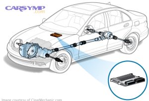
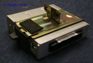
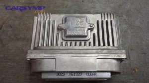
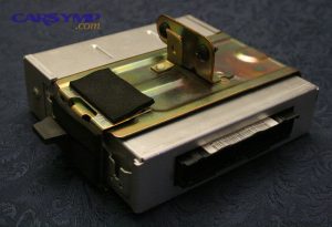
The ECU (Engine Control Unit) is the vehicle’s control computer for engine operation. Depending on the manufacturer, you may see the same “brain” labeled as ECU, ECM (Engine Control Module), or PCM (Powertrain Control Module). The name varies, but the diagnosis mindset stays the same: the ECU makes decisions based on sensor inputs, then commands actuators and systems to hit targets for power, drivability, and emissions.
At a high level, the ECU often controls or influences:
- Fuel delivery timing and quantity
- Ignition timing and misfire monitoring
- Idle control and throttle strategy (especially on drive-by-wire)
- Emissions systems (O2 sensor feedback, EVAP, catalyst monitoring)
- Cooling fan control and engine protection modes
- Torque requests that coordinate with the transmission (often in PCM setups)
A key diagnostic principle: the ECU is usually the “manager,” not the “muscle.” If an injector doesn’t fire, the injector or its wiring may be the culprit—even though the ECU is the thing commanding it. That’s why ECU vs sensor/wiring fault diagnosis is mostly about proving whether the ECU’s command is missing because the ECU is faulty—or because the ECU is being fed bad power, bad ground, bad data, or a broken network.
What is the difference between an ECU, ECM, and PCM?
ECU, ECM, and PCM are closely related labels for the engine control computer; “PCM” often implies it manages both engine and transmission, while “ECM/ECU” may focus mainly on engine control.
Then, the diagnostic takeaway is to match terminology to your vehicle documentation so you test the right module and circuits.
- ECU: generic term for an engine computer (also used broadly for any control unit).
- ECM: typically engine-focused module name used by many manufacturers.
- PCM: powertrain module—commonly integrates engine + transmission control logic.
In repair discussions, you’ll also hear “engine computer,” “engine brain,” or “control module.” Treat these as synonyms unless your service manual shows separate modules.
Can a bad ECU cause a check engine light, limp mode, or a no-start?
Yes—an ECU can trigger a check engine light, force limp mode, or even cause a no-start, because it manages critical engine decisions and may stop operation when it can’t trust inputs or communication.
However, the safer conclusion is this: those same outcomes are more often caused by power/ground faults, wiring damage, or sensor failures than a truly dead ECU.
Three common reasons the ECU can cause these issues:
- Critical sensor data becomes invalid (e.g., crank sensor signal missing), and the ECU cannot time fuel/ignition safely.
- The ECU enters protection strategy to prevent engine damage (limp mode, reduced power).
- The ECU loses internal function or communication and stops commanding outputs.
This is why you always test the basics (battery voltage, grounds, fuses, connectors) before labeling the ECU as failed.
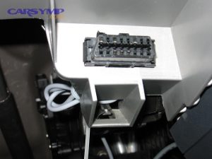
Is ECU diagnosis the same as an OBD2 code scan?
No—an OBD2 scan is data collection, while ECU diagnosis is the full troubleshooting workflow that confirms the root cause with tests and evidence.
Besides that, confusing “scan” with “diagnose” is one of the biggest reasons people replace the wrong parts.
A scan can tell you:
- What the ECU noticed (DTCs)
- Under what conditions it noticed it (freeze-frame)
- What the engine sensors are reporting now (live data)
But only diagnosis can tell you:
- Whether the ECU is receiving proper power/ground
- Whether wiring/connectors are intact under load
- Whether the ECU is communicating correctly
- Whether the ECU can command actuators when asked
What symptoms suggest an ECU fault vs a sensor or wiring problem?
ECU faults tend to show up as broad, inconsistent, or communication-related problems, while sensor or wiring issues usually follow a narrower pattern tied to a specific circuit, condition, or movement.
To begin, you’ll get better results if you treat symptoms as clues, not conclusions.
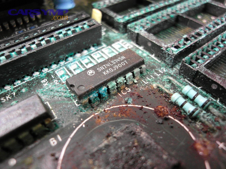
When drivers describe Car Symptoms like “random stalling,” “won’t start sometimes,” or “multiple warning lights,” it’s tempting to blame the ECU. But symptoms alone rarely prove it. A more accurate approach is to look for patterns: what repeats, what changes with heat or moisture, and whether the problem affects one subsystem or many.
A practical rule of thumb:
- One circuit acts up → suspect sensor/wiring/component first
- Many unrelated systems act up → suspect shared power/ground, network communication, or (less often) the ECU itself
What are the most common ECU-related symptoms drivers notice?
There are 7 common groups of ECU failure symptoms: no-start, stalling, intermittent misfires, erratic idle/throttle behavior, limp mode, repeated communication faults, and multiple “implausible” sensor readings across systems.
More specifically, these symptoms are more suspicious when they occur with stable power/ground and clean connectors.
Common symptom groups:
- No-start or intermittent start (cranks but won’t fire, or starts then dies)
- Stalling at idle, at stops, or randomly while driving
- Random misfires across multiple cylinders that don’t respond to ignition/fuel repairs
- Erratic throttle/idle (surging, hanging idle, unexpected reduced throttle response)
- Limp mode / reduced power with no obvious mechanical trigger
- Scanner cannot communicate with the engine module intermittently
- Multiple warning lights and multiple fault codes that don’t align to a single system
Even here, notice the wording: these are ECU-*related* patterns, not ECU-*proven* failures.
Which symptoms are more likely wiring/ground issues than an ECU failure?
Symptoms that change with bumps, temperature, moisture, or connector movement are more likely wiring, ground, or connector faults than an ECU failure.
Meanwhile, that’s great news because wiring and grounds are often cheaper to fix than modules.
High-suspicion wiring/ground indicators:
- Problem appears after rain or car wash (water intrusion)
- Problem changes when you wiggle the harness or tap the ECU area
- Symptoms worsen with vibration, rough roads, or engine movement
- You see green/white crust, swollen seals, or bent pins in connectors
- Blown fuses recur, especially ECU power supply fuses
- Voltage readings look fine “at rest,” but drop under load (hidden resistance)
This is where auto electrical repair basics—clean grounds, proper voltage drop testing, correct connector repair—solve more “bad ECU” complaints than ECU replacement does.
If multiple “random” codes appear at once, does that mean the ECU is bad?
No—multiple random codes usually point first to low voltage, poor grounds, connector corrosion, or network issues, because those conditions confuse the ECU and trigger cascading faults.
However, multiple codes can still be consistent with an ECU problem if you’ve already proven stable power/ground and solid communication wiring.
A better interpretation of “random” codes is: the ECU is reporting chaos—not necessarily creating it. If battery voltage dips during crank, a weak ground adds resistance, or the CAN network is noisy, you can get a flood of codes that disappear temporarily after clearing—then return once conditions repeat.
How do you diagnose ECU faults step-by-step (DIY workflow)?
You diagnose ECU faults by following a 7-step workflow—collect data, preserve evidence, confirm power/grounds, inspect connectors, verify communication, test commands, and only then consider ECU failure—so you can rule out the common causes first.
Then, this workflow helps you avoid replacing expensive parts without proof.

Below is a DIY-friendly path that mirrors the best parts of an ECU testing process at a shop, while keeping the steps safe for a home garage.
What is the safest “confirm → test → rule out” sequence for ECU diagnosis?
The safest sequence is: confirm symptoms, test with a scan tool and multimeter, then rule out power/ground/wiring/communication before concluding the ECU is faulty.
Next, treat each step as a “gate”—if you fail a gate, fix that issue before moving on.
Step 1: Confirm the complaint clearly
- Write down exactly what happens (crank/no-start, stalls hot, dies at stops, etc.).
- Note conditions: temperature, rain, time since last drive, fuel level, recent battery work.
Step 2: Scan for codes and save the data
- Read DTCs in all modules if possible.
- Save freeze-frame data and note readiness monitors.
- If the scanner shows Communication codes (often U-codes), highlight them—they’re often power/ground/network related.
Step 3: Check battery and charging health
- Low voltage can mimic module failure, especially during cranking.
Step 4: Confirm ECU power supplies and grounds
- Verify fuses, relays, and ground points.
- Use voltage drop testing under load (details later).
Step 5: Inspect ECU connectors and harness condition
- Look for ECU water damage and corrosion inspection signs: moisture trails, corrosion, pin damage.
Step 6: Verify module communication and network integrity
- Confirm whether the scanner can reliably connect.
- Interpret U-codes logically.
Step 7: Test ECU commands (when safe)
- Use bidirectional controls if available.
- If commands are missing and inputs/power/ground/network are proven good, the ECU becomes a stronger suspect.
At the end of this sequence, you’ll have evidence—not just a hunch.
Should you clear codes before testing?
No—do not clear codes before you capture freeze-frame data and confirm patterns, because clearing erases the best evidence of what the ECU saw when the fault occurred.
Besides that, clearing too early can reset readiness monitors and make the problem harder to reproduce.
Clear codes only after you:
- Save codes and freeze-frame
- Record battery voltage and any obvious wiring issues
- Make at least one repair or test change worth verifying
A smart habit: take photos of the scan results or export them if your tool supports it.
What evidence should you collect before blaming the ECU?
You should collect at least 6 pieces of evidence—symptom pattern, DTCs + freeze-frame, battery/charging readings, power/ground test results, connector/harness inspection results, and communication reliability—before suspecting the ECU.
More importantly, this evidence protects you from “parts cannon” decisions.
Evidence checklist:
- Symptom notes: When it fails, how it fails, how often
- DTC list: include “history” vs “current” status if supported
- Freeze-frame: RPM, coolant temp, load, voltage at time of fault
- Live data sanity checks: does coolant temp read plausible? TPS stable? battery PID stable?
- Power/ground tests: fuses, relays, voltage drops
- Connector inspection notes: corrosion, pin tension, water evidence
- Communication reliability: consistent connection to ECU or intermittent?
If you can’t answer these items, you’re not really diagnosing yet—you’re still guessing.
What should you check first before suspecting the ECU?
Before suspecting the ECU, check battery health, charging voltage, ECU fuses/relays, and ground integrity first—because unstable power or a weak ground can create ECU-like failures even when the module is healthy.
To better understand why, remember that the ECU is extremely sensitive to voltage stability during crank and under load.

Many “bad ECU” diagnoses are actually:
- A weak battery that drops voltage too low while cranking
- A corroded ground strap that adds resistance under load
- A failing relay that intermittently starves the ECU of power
- A connector that looks fine but has poor pin tension
Which power supply and ground checks rule out false ECU failures?
The three most important checks are: stable battery voltage (especially during crank), verified ECU power at the correct pins/fuses/relays, and low-resistance grounds confirmed with voltage drop testing.
Specifically, these checks target the shared foundations that everything else depends on.
Start with these:
- Battery health
- Measure resting voltage and observe voltage during crank if you can.
- If the engine cranks slowly or the dash flickers, suspect battery/connection issues first.
- Charging system sanity
- After the vehicle runs, verify that charging voltage is within normal range for most cars (often mid-13V to mid-14V depending on system and smart charging strategy).
- ECU fuses and relays
- Check ECU/ECM/PCM fuses (both engine bay and interior, depending on car).
- Don’t just look—confirm power is present on both sides of the fuse when it should be.
- Ground points and straps
- Inspect and clean grounds (battery negative to chassis, chassis to engine).
- Look for green corrosion, loose bolts, paint under ground lugs, or broken straps.
When these basics are unstable, the ECU can throw errors that look like internal failure.
What is a voltage drop test and why is it better than just “checking continuity”?
A voltage drop test measures how much voltage is lost across a wire/connection under load, making it better than continuity checks because it reveals hidden resistance that only appears when current flows.
Then, this method directly targets the kind of “intermittent” electrical problem that causes false ECU diagnoses.
Continuity can tell you a wire is not fully broken—but it cannot tell you the connection is good under load. A connector can pass continuity yet fail when current demand rises.
Basic voltage drop concept:
- Put the meter leads across the connection you want to test
- Run the circuit under load (crank, turn on loads, run fuel pump command, etc.)
- The reading shows how much voltage is being “wasted” in that connection
High voltage drop on an ECU ground or power feed can create everything from stalling to no-start.
Can a weak battery or charging issue mimic ECU failure?
Yes—a weak battery or charging issue can mimic ECU failure because low voltage can cause the ECU to reset, lose communication, log misleading codes, or stop commanding fuel/ignition during crank.
Moreover, fixing the power foundation often “fixes” the mystery symptoms without touching the ECU.
A classic pattern:
- Car cranks but won’t start
- Scanner shows communication trouble or weird sensor readings
- After a jump start, it works… for a while
- Then the problem returns
That’s why you treat power and grounds as the first gate in any serious ECU diagnosis.
How do you use an OBD2 scanner to support ECU diagnosis (without guessing)?
You use an OBD2 scanner to support ECU diagnosis by capturing codes, freeze-frame, readiness status, and live-data plausibility—then using that information to decide what electrical tests to run next.
Next, you’ll focus on patterns that distinguish “the ECU noticed a fault” from “the ECU is the fault.”
A scanner becomes powerful when you stop treating codes as parts to replace and start treating them as clues. A code rarely means “replace ECU.” Instead, it usually points to:
- A system that isn’t behaving as expected
- A circuit condition (open/short/implausible)
- A communication failure between modules
- A performance problem detected over time
What do DTC categories (P-codes vs U-codes) tell you about ECU vs network issues?
P-codes generally relate to powertrain/emissions faults, while U-codes are communication-related and often indicate network, power, or module connectivity problems rather than a single bad sensor.
However, the key is context: the same U-code can be caused by a module, wiring, or power issue.
Quick practical meaning:
- P0xxx / P1xxx: engine/powertrain faults (misfire, fuel trim, sensor range, catalyst efficiency, etc.)
- U0xxx: module communication faults (loss of communication, network errors)
When you see Communication codes, don’t panic. First ask:
- Can the scanner communicate with the ECU right now?
- Do multiple modules show U-codes pointing to the same missing module?
- Did the problem start after battery work, water intrusion, or harness repair?
U-codes are often the gateway to finding a broken power feed, ground, or network wire rather than proving the ECU is dead.
Which scanner data points are most useful for confirming/denying an ECU problem?
The most useful scanner data points are freeze-frame voltage and conditions, live battery/charging PID (if available), RPM signal during crank, throttle/accelerator agreement, coolant temperature plausibility, and communication consistency.
More specifically, you’re looking for “impossible” readings that point to wiring/sensor faults.
High-value checks:
- RPM during crank: if RPM stays at 0 while cranking, suspect crank sensor/circuit before ECU.
- Coolant temp plausibility: extreme values at cold start can indicate sensor/circuit issues.
- Throttle vs pedal agreement: large mismatch can indicate wiring/throttle issues; sometimes ECU enters limp.
- Battery voltage PID: if the ECU reports voltage drops when the symptom occurs, prioritize power/ground testing.
- Readiness monitors: if recently cleared, you lose timeline context.
Your scanner doesn’t need to be expensive to do these checks—many mid-level tools can.
Basic code reader vs bidirectional scan tool—what’s the difference for ECU testing?
A basic code reader is best for reading/clearing codes and some live data, while a bidirectional scan tool is best for testing ECU commands because it can run actuator tests and request functions directly from modules.
On the other hand, you can still do meaningful diagnosis with a basic reader if you combine it with careful electrical testing.
Bidirectional advantages:
- Command fuel pump (on some vehicles)
- Cycle fans or solenoids
- Run throttle relearn procedures
- Access more module data and status
For ECU diagnosis, bidirectional tests are valuable because they can show whether the ECU can still command outputs when asked—assuming power/ground and wiring are proven good.
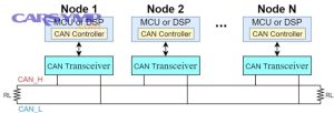
How can you test ECU wiring, connectors, and the CAN bus for communication problems?
You test ECU wiring and connectors by inspecting for damage/corrosion and validating power/ground integrity under load, and you test CAN communication by confirming stable scanner connectivity and checking for network-related fault patterns (often U-codes).
Then, you use the results to separate “module failure” from “network failure.”

Communication problems are a major reason DIYers get stuck. If the scan tool can’t talk to the ECU, you can’t trust codes or data—so your workflow shifts toward power, ground, connector, and network integrity checks.
You may see symptoms like:
- Scanner intermittently connects or fails to connect
- Multiple modules report loss-of-communication with the ECU
- Vehicle has widespread warning lights and weird behaviors
This is also where careful auto electrical repair practices matter: correct pin-fit repair, sealed splices, and proper harness support.
What is “loss of communication” and how does it show up during diagnosis?
Loss of communication means a module (or the scanner) cannot reliably exchange data with the ECU over the vehicle network, often showing as U-codes, failed module scans, or intermittent connectivity.
Besides that, it often points to a shared power/ground issue or a network wiring fault—not instantly to a dead ECU.
Common signs:
- “No communication with ECM/PCM” message on scan tool
- U-codes stored in multiple modules referencing the same missing module
- Vehicle behaviors like no-start, limp mode, or inoperative gauges when the network is disrupted
If communication loss is intermittent, suspect:
- Loose ground or power feed
- Connector pin tension problems
- Water intrusion
- Harness damage near high-movement areas
What connector and harness checks catch most ECU communication issues?
The three most effective checks are: connector corrosion/pin damage inspection, harness rub/chafe inspection, and verifying that ECU power and grounds remain stable while the fault is happening.
More importantly, this is where you look for the real-world causes behind “mystery” network errors.
Use this checklist:
- Connector inspection
- Look for moisture, corrosion, bent pins, pushed-back pins
- Confirm seals are intact and connectors latch firmly
- Perform ECU water damage and corrosion inspection around the ECU location and harness entry points
- Harness inspection
- Look for rub-through near brackets, engine edges, battery tray areas
- Check areas exposed to heat (near exhaust components)
- Look for prior repairs: twisted wires, unsealed splices, cheap crimp connectors
- Wiggle test (carefully)
- With the engine idling (if possible), gently move the harness near connectors
- If symptoms appear/disappear, you’ve found a high-suspicion area
ECU failure vs CAN wiring fault—how do your test results differ?
ECU failure is more likely when the ECU has correct power/grounds yet still cannot communicate or cannot command outputs, while a CAN wiring fault is more likely when multiple modules lose communication in a pattern and the fault changes with harness/connector conditions.
However, you only get a reliable conclusion when you follow the testing order.
A helpful comparison:
- CAN/network wiring fault clues
- U-codes across multiple modules
- Symptoms fluctuate with movement/moisture
- Scanner connectivity changes rapidly
- Other modules show network errors too
- ECU internal fault clues
- Power/grounds verified stable at ECU
- Connectors clean and tight
- Network wiring checks out
- ECU still fails to communicate or fails actuator commands consistently
According to a study by Tennessee Tech University from the Department of Electrical and Computer Engineering, in 2023, a CAN-bus intrusion detection system achieved accuracy up to 99.9%, showing how measurable patterns in CAN traffic can be analyzed to confirm network-level issues rather than guessing from symptoms alone.
When is the ECU actually bad, and what are your repair options?
The ECU is most likely bad when you can prove stable power/grounds, clean connectors, and valid wiring/communication—and the ECU still fails communication or fails to command outputs consistently under the same conditions.
Next, once the ECU is a justified suspect, you choose between ECU repair vs replacement options based on cost, programming needs, and risk tolerance.
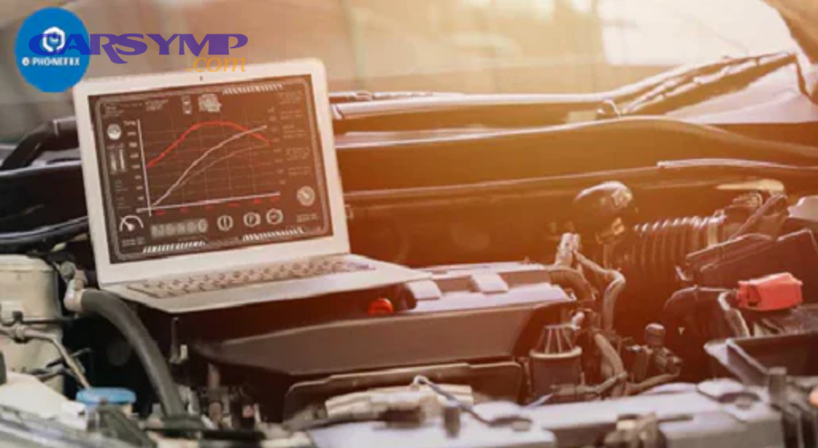
At this stage, you’re not asking, “Could it be the ECU?” You’re asking, “Have I proven it’s not the basics?”
A practical “ECU is now a strong suspect” checklist:
- ECU power feeds present at the right times
- ECU grounds show low voltage drop under load
- No recurring fuse/relay/power interruptions
- Connectors show no corrosion or water intrusion
- Harness checks show no obvious opens/shorts
- Communication faults persist despite known-good power/ground
- Outputs fail to respond even when commanded (where testable)
If power/grounds are good and communication is still failing, is ECU replacement justified?
Sometimes yes—ECU replacement is justified when power and ground integrity are proven, connectors and wiring are confirmed, and the ECU still cannot communicate or cannot function consistently.
However, the safer move is to consider professional confirmation when the decision is expensive or programming-heavy.
Why “sometimes” matters:
- Some vehicles require module programming and immobilizer matching; replacing without proper setup can create a new no-start.
- Some communication failures are network-related and can look like a dead ECU until deeper testing is done.
- Used modules can introduce new variables (wrong calibration, hidden damage, mismatched security).
This is also the point where an ECU testing process at a shop can save money if it prevents an unnecessary module purchase.
ECU repair vs replacement—what’s cheaper, safer, and faster?
Repair often wins on cost when the failure is repairable and the shop offers warranty, replacement wins on speed when parts and programming are readily available, and “used” wins on price but carries the highest risk.
On the other hand, the “best” option depends heavily on your vehicle’s immobilizer and programming requirements.
Here’s a clear comparison:
- ECU repair (send-out or specialist)
- Pros: often cheaper than new, may preserve original programming/immobilizer data, warranty possible
- Cons: downtime, not all failures are repairable, quality varies by vendor
- New/reman replacement
- Pros: predictable part quality, warranty, supported programming path
- Cons: often higher cost, may require dealer-level programming, availability varies
- Used ECU
- Pros: lowest upfront cost, quick availability in some cases
- Cons: When to consider a used ECU risks becomes the main question—because the module may be incompatible, require cloning, or fail soon due to unknown history
Below is a ECU diagnosis cost estimate table to help you set expectations. It shows common price ranges you may encounter; actual pricing depends on vehicle, region, and the complexity of testing/programming.
| Service item | What it usually includes | Typical cost range (USD) |
|---|---|---|
| Basic scan / code read | Read/clear codes, limited data | $0–$100 |
| Diagnostic testing | Data capture + electrical checks + pinpoint tests | $120–$250+ |
| Network/communication diagnosis | Deeper testing for U-codes and module comm | $180–$350+ |
| ECU programming | Flashing, coding, setup procedures | $150–$400+ |
| ECU repair (specialist) | Repair of known failure points, bench verification | $200–$800+ |
| ECU replacement (part only) | Used/reman/new ECU | $150–$1500+ |
A smart strategy: pay for diagnosis once—then apply that cost toward the correct fix rather than paying repeatedly for guesses.
What should you ask a shop or ECU repair service before paying?
You should ask for proof of testing, warranty terms, programming requirements, and the root cause of failure, because a good provider will explain what failed and why—then tell you how they verified it.
More importantly, these questions keep you from buying a module that can’t be installed successfully.
Ask these:
- How do you confirm the ECU is faulty? (What tests, what evidence?)
- Do you bench test the ECU? What does “pass/fail” mean?
- What warranty is provided, and what voids it?
- Will ECU programming and immobilizer pairing be required on this vehicle?
- If using a used module, how do you ensure compatibility?
- What caused the ECU to fail? (Water intrusion, over-voltage, harness short?)
- Do you test and advise on the underlying cause? (So the next ECU doesn’t die too)
This is also where “No-start ECU-related causes” should be discussed explicitly—because many no-starts are security, power, or crank-signal issues, not a dead ECU.
What advanced ECU failure scenarios and edge cases can affect diagnosis?
Advanced ECU issues usually involve security/immobilizer logic, water intrusion, intermittent heat-related failures, or programming mismatches—cases where symptoms are real but the root cause isn’t obvious from basic scanning alone.
To sum up the main content and expand responsibly, these edge cases help you know when DIY should stop and expert testing should begin.
How does immobilizer/security (no-start) differ from a true ECU failure?
Immobilizer-related no-start differs because the ECU may be healthy but prevented from enabling fuel/ignition until the correct security handshake occurs, while a true ECU failure prevents operation even when security conditions are satisfied.
Next, this distinction matters because replacing an ECU without addressing security often creates a permanent no-start.
Typical immobilizer pattern:
- Cranks but won’t start
- Security light behaves abnormally
- Codes may appear in body/security modules
- ECU may show “start not authorized” style messages (tool-dependent)
This is where ECU programming and immobilizer pairing becomes non-negotiable. Many vehicles require the ECU and immobilizer system to “agree” before the engine will start. In these cases, the ECU itself might not be failed—it might simply be unmatched or locked out.
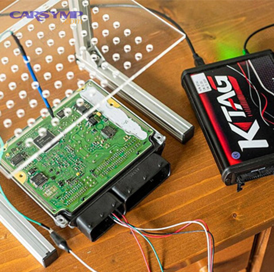
What is ECU bench testing and when is it the best next step?
ECU bench testing is a controlled test of the ECU outside the vehicle to verify internal function, common failure points, and sometimes input/output behavior—making it the best next step when in-car tests strongly suggest ECU failure but replacement is costly or programming-heavy.
Besides that, bench testing can identify repairable failures like internal shorts, damaged drivers, or corrosion.
Bench testing is most useful when:
- You’ve verified power/ground/wiring and still have no communication
- The ECU behaves inconsistently (works hot/cold only)
- You suspect internal damage from water intrusion or voltage events
- You want to confirm failure before buying a new/reman module
This aligns with the ECU testing process at a shop or specialist: prove the basics, confirm fault, then recommend repair or replacement with documentation.
What are the most common root causes of ECU damage (water intrusion, low voltage, jump-starts)?
There are 4 common root causes of ECU damage: water intrusion/corrosion, over-voltage or unstable voltage events, shorts caused by harness damage, and thermal stress that cracks solder joints or weakens internal components over time.
More specifically, preventing repeat failure matters as much as replacing the ECU.
Common causes and what to check:
- Water intrusion and corrosion
- Leaks near cowl, windshield, HVAC drains, or ECU mounting location
- Corrosion at connectors and inside module housings
- Evidence: moisture trails, green crust, musty odor, intermittent faults after rain
- This is exactly why ECU water damage and corrosion inspection belongs in every serious diagnostic workflow.
- Voltage events
- Weak battery + repeated jump starts
- Poor grounds causing spikes/instability
- Alternator issues and transient events
- Harness shorts
- Wires rubbed through and occasionally short to ground or power
- Aftermarket wiring mistakes (alarms, remote start, audio)
- Heat and vibration
- Intermittent faults that appear hot, disappear cold (or vice versa)
- Internal solder cracks or component fatigue
The most important mindset: don’t install a replacement ECU until you’ve addressed the cause—otherwise the next ECU may fail the same way.
Can you install a used ECU without programming or “cloning”?
Sometimes yes, but often no—many vehicles require programming, coding, or ECU programming and immobilizer pairing, and a used ECU can be incompatible even if it physically plugs in.
However, you can reduce risk if you verify part numbers, calibration compatibility, and security requirements before purchase.
When to consider a used ECU risks becomes your decision point if:
- The vehicle has immobilizer/security integration
- The ECU stores VIN or configuration data
- The replacement must match exact hardware/software variants
If you’re going used, treat it like a controlled experiment:
- Confirm exact part number and compatible supersessions
- Confirm whether cloning is needed (depends on platform)
- Confirm whether keys/immobilizer will need reprogramming
- Choose a source with return policy and testing documentation
Evidence (if any)
- CAN/ECU communication reliability and measurable patterns in CAN traffic are discussed in academic research; a study from Tennessee Tech University reports machine-learning CAN analysis achieving up to 99.9% accuracy in classifying intrusion patterns, illustrating how structured network analysis can outperform guessing when diagnosing communication-level problems. (pmc.ncbi.nlm.nih.gov/articles/PMC10099193/)